background image

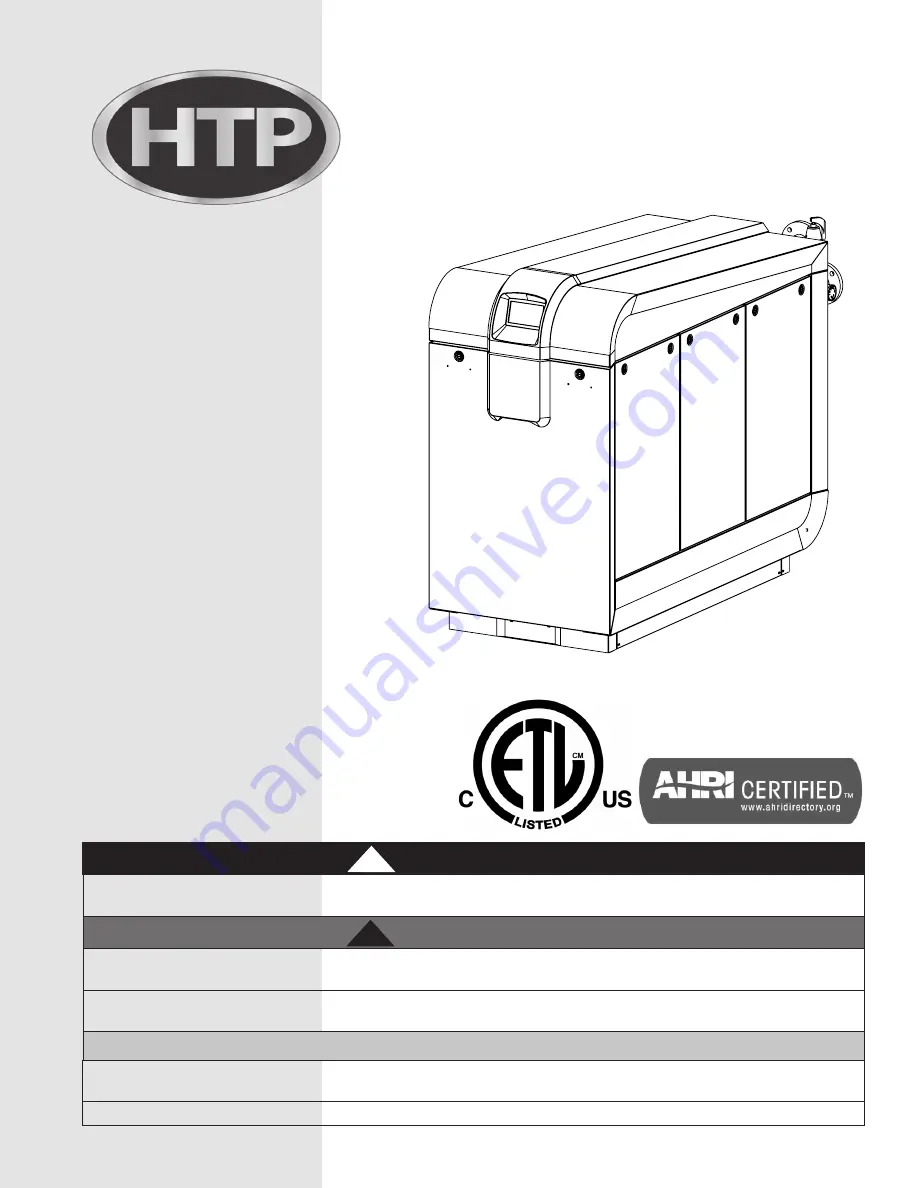
Elite XL®

Commercial Boilers 

Installation

Start-Up

Maintenance

Parts

Warranty

ELX-400 / 500 / 650 / 800 / 1000 / 1500 / 2000 Models*

*”B” Denotes Boiler Models, 

”N” Denotes Natural Gas, “LP” Denotes Propane, 

and “F” Denotes Floor Mount Models

Example Model: ELX-1000FBN

DANGER

!

This manual must only be used by a qualified installer / service technician. Read all instructions in this manual before installing. 

Perform steps in the given order. Failure to do so could result in substantial property damage, severe personal injury, or death.

NOTICE

HTP reserves the right to make product changes or updates without notice and will not be held liable for typographical errors 

in literature.

NOTE TO CONSUMER: PLEASE KEEP ALL INSTRUCTIONS FOR FUTURE REFERENCE.

272 Duchaine Blvd.

New Bedford, MA 02745

www.htproducts.com 

lp-666 Rev. 003 Rel. 001 Date 2.25.20

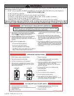
WARNING

!

Improper installation, adjustment, alteration, service, or maintenance could void product warranty and cause property 

damage, severe personal injury, or death.

Heat Exchanger Bears the ASME “H” 

Stamp

California Proposition 65 Warning: This product contains chemicals known to the State of California to cause cancer, birth 

defects, or other reproductive harm.

Summary of Contents for Elite XL ELX-1000

Page 1: ...sonal injury or death NOTICE HTP reserves the right to make product changes or updates without notice and will not be held liable for typographical errors in literature NOTE TO CONSUMER PLEASE KEEP ALL INSTRUCTIONS FOR FUTURE REFERENCE 272 Duchaine Blvd New Bedford MA 02745 www htproducts com lp 666 Rev 003 Rel 001 Date 2 25 20 WARNING Improper installation adjustment alteration service or mainten...

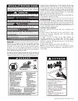
Page 2: ...any appliance Do not touch any electrical switch do not use any phone in your building Immediately call your gas supplier from a neighbor s phone Follow the gas supplier s instructions If you cannot reach your gas supplier call the fire department Installation and service must be provided by a qualified installer service agency or the gas supplier Improper installation adjustment alteration servic...

Page 3: ...r the Installer This boiler must be installed by qualified and licensed personnel The installer should be guided by the instructions furnished with the boiler and by local codes and utility company requirements In the absence of local codes preference should be given to the National Fuel Gas Code ANSI Z223 1 latest version Installations Must Comply With Local state provincial and national codes la...

Page 4: ... in the boiler software This feature may be over ridden as described below in specific installations The boiler control is equipped with an outdoor sensor override for use with building management systems or in cascaded systems for systems with total input of 300 000 BTU hr or greater See statement below for an important notice on the use of the override IMPORTANT In accordance with Section 325 f ...

Page 5: ...l injury or death C Line Voltage Wiring for Standard Boiler 31 D Alarm Connections 31 E Low Voltage Connections for Standard Boiler 31 F Thermostat 31 G Outdoor Sensor 31 H Indirect Sensor 31 I UL 353 Internal Low Water Cut Off Factory Installed 31 J Wiring of Cascade System Communication Bus 31 K Cascade Master System Pump and Sensor Wiring 32 L Cascade Follower Pump and Sensor Wiring 32 M Variab...

Page 6: ...rate of the boiler Components included with the boiler Outdoor Sensor 7250P 319 Intake Exhaust Screens 400 500 Models 7550P 995 650 1000 Models 7550P 996 1500 2000 Models 7550P 997 Installation Manual and Warranty User s Information Manual CSD 1 Form H 3 Data Sheet A What s in the Box B How the Boiler Operates Condensing technology intelligently delivers highly efficient hydronic heating while max...

Page 7: ...Condensate Removal Pump 554200 Stainless Steel Steel Heat Exchanger The highly efficient heat exchanger is designed to use the cold water return from the system and extract the last bit of heat before it is exhausted Modulating Combustion System The combustion system modulates the output of the burner during operation to match system demand and achieve the control set point while in operation The ...

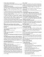
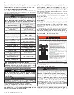
Page 8: ...p and drain lines from sustained freezing conditions Failure to take precautions could result in property damage severe personal injury or death 2 Check for nearby connections to System water piping Venting connections Gas supply piping Electrical power Condensate drain 3 Check area around boiler Remove any combustible materials gasoline and other flammable liquids WARNING Failure to keep the boil...

Page 9: ...ure of the installation location are sufficient to support the full installed weight of the boiler including water content of the heat exchanger and related piping Failure to ensure the floor and structure of the installation location are structurally sound before installation of the boiler can result in structural failure substantial property damage severe personal injury or death LP 666 R 01 03 ...

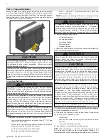
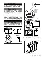
Page 10: ...rty damage and personal injury CAUTION Precautions If the boiler is located in a residential garage per ANSI Z223 1 Install the boiler burner and ignition devices a minimum of 18 above the floor of the garage This will ensure the burner and ignition devices are well off the floor When raising the boiler ensure the entire bottom and fully filled weight of the boiler are fully supported Locate or pr...

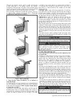
Page 11: ...ould have a free area of one square inch per 1 000 BTU hr 22cm2 kW of the total input of all appliances in the space but not less than 100 square inches 645cm2 If the confined space is within a building of tight construction air for combustion must be obtained from the outdoors as outlined in the Venting section of this manual CAUTION When drawing combustion air from the outside into the mechanica...

Page 12: ...w 1 Seal any unused openings in the common venting system 2 Visually inspect the venting system for proper size and horizontal pitch to determine if there is blockage leakage corrosion or other deficiencies that could cause an unsafe condition Closed loop water must be free of corrosive chemicals sand dirt and other contaminates It is up to the installer to ensure the water J Water Chemistry Requi...

Page 13: ...arged particles that are dissolved in water The greater the amounts of TDS present the higher the corrosion potential due to increased conductivity in the water If using softened water to fill the appliance it is still possible to have high TDS This water can be corrosive Consult local water treatment companies for other treatment solutions to reduce this affect NOTE The amount of Hardness ppm mg ...

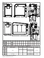
Page 14: ...1000 1500 2 1 2 Flange 8 8 1 1 2 1 PVC 2000 2 Table 2 ELX Adapter Dimensions and Specifications R C M L E Q P G K F H O D N J A B D E F G H J L M N R Q P O K LP 666 P 08 23 19 ELX1500 2000 ELX400 1000 C A B MODEL A B C D E F G H J K L M N O P Q R ELX400 500 41 0 26 0 40 7 17 9 35 0 4 1 10 1 10 5 12 6 16 1 20 5 22 0 6 1 8 1 25 8 35 0 2 8 ELX650 1000 56 5 ELX1500 60 8 31 8 66 5 39 2 44 8 51 2 3 4 7 ...

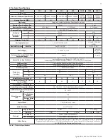
Page 15: ...perature Range 33 104o F 0 6 40o C Product Approvals and Requirements ANSI Z21 13 CSA 4 9 CSD 1 ASME Code Ignition System Direct Electronic Spark Ignition Flame Rectification Burner System Premixed Fuel Modulation Stainless Steel Burner Gas Valve System Pneumatic Gas Valve Dimensions in Inches W 26 31 8 H 41 60 8 D 40 7 56 5 66 5 79 Boiler Water Content Gallons 3 8 4 3 5 6 6 6 8 1 12 9 16 25 Minim...

Page 16: ...r Use one wrench to prevent the boiler return or supply line from turning Failure to prevent piping connections from turning could cause damage to boiler components The control module uses temperature sensors to provide both high limit protection and modulating temperature control The control module also provides low water protection by sensing the water level in the heat exchanger Some codes juri...

Page 17: ...the boiler circulator valves and other components Observe minimum 1 clearance around all uninsulated hot water pipes when openings around pipes are not protected by non combustible materials On a boiler installed above radiation level some states and local codes require a low water cut off device This is provided standard on the boiler Check with local codes for additional requirements If the boil...

Page 18: ...ple 5 1000 boilers with a design of 30oF temperature rise with each boiler having an individual flow rate of 64 GPM To correctly size the manifold feeding these boilers you would need a pipe size of 6 Model 20oF 30oF 40oF GPM Ft Hd GPM Ft Hd GPM Ft Hd 400 39 12 0 26 7 2 19 4 0 500 48 11 4 32 5 4 24 3 2 650 63 11 5 42 6 2 31 4 0 800 77 12 52 6 39 3 1000 96 14 0 64 7 48 4 7 1500 146 16 97 7 6 73 4 7...

Page 19: ...r line 15 PSI nominal on the system return Check temperature and pressure gauge when operating It should read a minimum pressure of 12 PSI 6 Install a circulator as shown in piping details this section Make sure the circulator is properly sized for the system and friction loss 7 Install an expansion tank on the system supply Consult the tank manufacturer s instructions for specific information rel...

Page 20: ...ations NOTE The boiler circulator cannot be used for a zone It must only supply the boiler loop 2 Install a separate circulator for each zone 3 Connect DHW domestic hot water piping to indirect storage water heater as shown in Applications N Multiple Boilers 1 Connect multiple boilers as shown in Applications 2 All piping shown is reverse return to assure balanced flow throughout the connected boi...

Page 21: ...t be installed on the cold water line per 248 CMR 11 See Multiple Boiler Manifold Piping chart this manual when sizing and installing a multiple boiler system WARNING The piping will not support the weight of the circulators Refer to the circulator manufacturer s instructions to properly support the circulator Failure to comply with these instructions could result in property damage severe persona...

Page 22: ...ilure to do so could result in property damage severe personal injury or death DANGER Due to the extreme flammability of most glues cements solvents and primers used to join plastic exhaust vent and intake pipes explosive solvent vapors must be cleared from all vent piping before start up Avoid using excess cement or primer as this may pool in the vent pipes Vent assemblies should be allowed to cu...

Page 23: ... these installed components Doing so WILL VOID appliance warranty PVC CPVC pipe and fittings of the same diameter are considered interchangeable The use of cellular core PVC ASTM F891 cellular core CPVC or Radel polyphenolsulfone in exhaust venting systems is prohibited Covering non metallic vent pipe and fittings with thermal insulation is prohibited DO NOT connect PVC CPVC to Polypropylene witho...

Page 24: ...at may be opened Direct Vent 1 foot 3 feet 91 cm Power Vent 4 ft below or to side of opening 1 ft above opening C Clearance to permanently closed window D Vertical clearance to ventilated soffit located above the terminal within a horizontal distance 2 feet 61 cm from the center line of the terminal E Clearance to unventilated soffit F Clearance to outside corner G Clearance to inside corner H Cle...

Page 25: ...or proper installation NOTE Clean and dry the boiler adapters DO NOT use primer or cement on the boiler adapters a Clean all pipe ends and fittings using a clean dry rag Moisture will retard curing and dirt or grease will prevent adhesion b Dry fit piping to ensure proper fit up before assembling any joint The pipe should go a third to two thirds into the fitting to ensure proper sealing after cem...

Page 26: ...ion air intake and ii The letters shall be sized equal to a minimum of the pipe diameter However for piping with a diameter exceeding two inches said lettering does not need to be larger than two inches G Applications 1 Direct Vent Installation of Exhaust and Intake If installing a direct vent option combustion air must be drawn from the outdoors directly into the boiler intake and exhaust must te...

Page 27: ... the terminations are screened to prevent blockage caused by debris or birds 12 MIN MAINTAIN 12 MINIMUM CLEARANCE ABOVE HIGHEST ANTICIPATED SNOW LEVEL OR GRADE WHICHEVER IS GREATER TYP EXTERIOR WALL EXHAUST INTAKE 1 MIN 06 23 15 LP 505 A Insert Intake Exhaust Screen into Open End of Elbow Insert Intake Exhaust Screen into Coupling Two Pipe Sidewall Venting with Intake Elbow and Coupling Exhaust 40...

Page 28: ...re inches Metal louvers or screens reduce the free area of a combustion air opening a minimum of approximately 25 Check with louver manufacturers for exact net free area of louvers Where two openings are provided one must be within 12 of the ceiling and one must be within 12 of the floor of the mechanical room Each opening must have a net free area as specified in Table 11 Single openings shall co...

Page 29: ...from backing up into the combustion system See Figure 22 for condensate connection and cleanout locations Condensate from the boiler is slightly acidic with a pH of 3 2 4 5 To avoid long term damage to the drainage system and to meet local code requirements HTP recommends neutralizing condensate with a Condensate Neutralizer Kit Part 7350P 611 The neutralizer kit connects to the drain system and c...

Page 30: ...pen to the atmosphere to prevent a vacuum that could obstruct the flow of condensate from the boiler To prevent sagging and maintain pitch condensate piping should be supported with pipe supports When installing a condensate pump select one approved for use with condensing boilers and furnaces The pump should have an overflow switch to prevent property damage from condensate spillage Part 7 Wiring...

Page 31: ...cipator and it is connected directly to the boiler the anticipator should be set at 1 amps If the thermostat is connected to other devices the anticipator should be set to match the power requirements of the device it is connected to See the instruction manual of the connected devices for further information strips for line voltage and low voltage wiring Special jacks are provided for trouble free...

Page 32: ...ed units be installed as depicted in Figure 27 Leave the plug installed in the J6 port on the Master boiler Remove the plug on intermediate Follower boilers Move the plug to the J7 port on the final Follower boiler 2 Use standard CAT3 or CAT5 computer network patch cables to connect the communication bus between each of the boilers These cables are readily available at any office supply computer e...

Page 33: ...jumper plug from one of the unused pigtails 3 Connect the high gas pressure switch to the pigtail that you removed the jumper plug from P Optional Low Gas Pressure Switch 1 If an optional low gas pressure switch is used it should be installed on the side of the gas valve This is normally closed and will open if the pressure goes below 2 w c on the inlet side 2 Locate the two pigtails hanging from ...

Page 34: ...LE BOILER AND CASCADE MASTER LP 666 X 09 20 19 REQUIRED WHEN PUMP CURRENT 2 AMPS 2A 2A 2A 15A Figure 25 Cascade Master and Single Boiler High Voltage Wiring 400 1500 Models BLACK HOT WHITE NEUTRAL GREEN GROUND POWER SWITCH BLOWER BLK BLU BLACK PUMP RELAY BOILER PUMP L N G 120V LINE 120V NEUT 120V GND LINE VOLTAGE IN 120VAC 5V DC USB NC NO ALARM PUMP POWER NC NO L N G S D C SG SN SL DG DN DL CG CN ...

Page 35: ...11 20 1 10 BIC 928 0 10 VOLT OUT B S T O D ELX 400 2 0 LOW VOLTAGE CUSTOMER CONNECTION BOARD SINGLE BOILER AND CASCADE MASTER LP 666 X2 09 18 19 SYSTEM SENSOR THERMOSTAT OUTDOOR SENSOR DHW SENSOR CASCADE BUS TERMINATION PLUG INSTALLED HERE IN FINAL CASCADED BOILER CASCADE BUS TERMINATION PLUG INSTALLED HERE Figure 28 Cascade Master and Single Boiler Low Voltage Wiring and Cascade Follower Low Volt...

Page 36: ...FERENCES FIELD CONNECTION BOARD DUAL FLUE SENSOR LWCO PROBE X7 12 X6 11 X6 10 S3 S4 S1 S2 X6 12 B A G B A G P5 3 P5 2 P5 1 PWM 24V HALL NEG X9 7 X9 6 X9 4 LED3 P3 2 P2 2 P2 3 F1 P10 4 P10 2 P10 7 P10 8 X9 1 MANUAL RESET HIGH LIMIT M F X7 9 X7 19 OPTIONAL BLK WHT GRN HMI DISPLAY BRN TAN YEL ORN WHITE BROWN RED PINK GRN RED LT GRN LT BLUE RED RED BLUE GRY BLUE BLK BLUE RED BLUE RED ORN PINK RED BLK ...

Page 37: ... trouble free cascade system wiring using standard CAT3 or CAT5 patch cables C Line Voltage Wiring for Standard Boiler NOTE A termination plug is included in the CAT 3 CAT 5 Bus Connection Point labeled J6 in Figure 34 DO NOT REMOVE THIS PLUG Doing so will affect boiler operation and void warranty 1 All high voltage cables should enter the boiler through the provided knock out holes as shown in Fi...

Page 38: ...f injury or death due to scalds WARNING Caution should be used to ensure neither of these terminals becomes connected to ground NOTE If sensor wires are located in an area with sources of potential electromagnetic interference EMI the sensor wires should be shielded or the wires routed in a grounded metal conduit If using shielded cable the shielding should be connected to the common ground of the...

Page 39: ...rsely if the Delta T is less than the desired setting the pump will decrease speed and flow to compensate NOTE This feature may be used in Primary Secondary piping arrangements ONLY Variable Speed Pumping Wiring 1 On the High Voltage Field Connection Board connect the Line of an externally provided 120VAC service to the TOP terminal of the three terminal barrier strip labelled P2 NO Normally Open ...

Page 40: ... RELAY N LINE IN LINE IN L N L SYSTEM PUMP EXTERNAL RELAY N LINE IN 5A 5A 5A 5A 5A 5A 2000 MODEL HIGH VOLTAGE CUSTOMER CONNECTION BOARD SINGLE BOILER AND CASCADE MASTER Figure 31 Cascade Master and Single Boiler High Voltage Wiring 2000 Model 2 Insert the control probe into the control well 3 Secure the high limit manual reset box to the control well 4 Locate and disconnect the red high limit manu...

Page 41: ...T RED HOT BLACK HOT WHITE NEUT GREEN GRND LINE VOLTAGE IN 208VAC 3 PH NO C NC ALARM LINE IN L N L BOILER PUMP EXTERNAL RELAY N LINE IN LP 666 X4 09 20 19 5A 5A 5A 5A 5A 5A 2000 MODEL HIGH VOLTAGE CUSTOMER CONNECTION BOARD CASCADE FOLLOWER Figure 33 Cascade Follower High Voltage Wiring 2000 Model ...

Page 42: ... 18 19 SYSTEM SENSOR THERMOSTAT OUTDOOR SENSOR DHW SENSOR CASCADE BUS TERMINATION PLUG INSTALLED HERE IN FINAL CASCADED BOILER CASCADE BUS TERMINATION PLUG INSTALLED HERE Figure 34 Cascade Termination Plug Detail Figure 35 Cascade Master and Single Boiler Low Voltage Wiring and Cascade Follower Low Voltage Wiring 5VDC TO DONGLE POWER SWITCH FROM HVCB 1 TO BIC928 TO GAS VALVE J11 J2 J3 X11 J5 J4 U1...

Page 43: ...1 OUT J5 2 N OUT J5 1 GND 5V J11 4 L1 IN J11 3 N IN J11 1 GND J2 3 L1 IN J2 2 N IN J2 1 GND 7550 053 HV INTERFACE BLK WHT GRN J4 USB CABLE WI FI DONGLE POWER J11 4 L1 IN J11 3 N IN J11 1 GND J2 3 L1 IN J2 2 N IN J2 1 GND 7550 052 HV CCB P1 L3 L2 L1 N G 208 3P IN J1 1 L3 OUT J1 2 L2 OUT J1 3 L1 OUT BLUE RED BLK FS6 LINE IN N P7 NO C NC NO C NC FS5 P6 DHW PUMP FS4 LINE IN N P5 NO C NC NO C NC FS3 P4...

Page 44: ...Y MANUAL SHUT OFF FIELD SUPPLIED UNION DRIP LEG LP 666 H 10 25 18 REQUIRED Figure 38 Gas Connection 1500 2000 Models The gas connection on the boiler is 1 NPT for 400 650 models 1 1 4 NPT for 800 1000 models 1 1 2 NPT for 1500 models and 2 NPT 2000 models It is mandatory that this fitting is used for connection to a field fabricated drip leg as shown in the illustration per the National Fuel Gas C...

Page 45: ...20 1160 1020 928 854 794 2 1 2 6400 4400 3530 3020 2680 2430 2230 2080 1950 1840 1630 1480 1360 1270 3 11300 7780 6250 5350 4740 4290 3950 3670 3450 3260 2890 2610 2410 2240 4 23100 15900 12700 10900 9660 8760 8050 7490 7030 6640 5890 5330 4910 4560 5 41800 28700 23000 19700 17500 15800 14600 13600 12700 12000 10600 9650 8880 8260 Table 12 Gas Supply Piping Size Chart for Boilers from NFPA 54 The ...

Page 46: ... THIS ADJUSTMENT COULD AFFECT CO CO LEVELS MAKE SURE THE LEVELS CORRESPOND TO THE CHART IN THIS MANUAL Figure 41 650 2000 Model Gas Valve If Necessary Use 40 Torx to Adjust Offset and Hex to Adjust the Throttle DANGER Do not do a gas conversion on this boiler without an officially approved conversion kit and instructions supplied by HTP Failure to use a conversion kit when converting the boiler to...

Page 47: ...must be replaced periodically due to degradation of inhibitors over time Follow all fluid manufacturer instructions NOTE Boiler failure due to improper water chemistry is not covered by warranty B Check for Gas Leaks WARNING Before starting the boiler and during initial operation smell near thefloorandaroundtheboilerforgasodorantoranyunusualodor Remove boiler front door and smell interior of boile...

Page 48: ...ts the burner Do not try to light the burner by hand 2 BEFORE OPERATING Smell all around the boiler area for gas Be sure to smell next to the floor because some gas is heavier than air and will settle on the floor 3 WHAT TO DO IF YOU SMELL GAS Do not try to light any boiler Do not touch any electric switch do not use any phone in your building Immediately call your gas supplier from a neighbor s p...

Page 49: ...Navigation Bar HTP Logo and Home Tapping the HTP Logo or Home will return the installer user to the Home Screen The Home Screen allows the installer user quick access to appliance internal operating temperatures external temperature sensor readings current CH and DHW setpoints and actual temperatures appliance modulation percentage operation details and a Reset key History The History screens allo...

Page 50: ...s complete when the system sensor is equal to the set point temperature The master boiler control will extinguish all boilers that may be lit If the demand decreases the firing rate command and amount of boilers lit will decrease exactly opposite as described above Whenever the master boiler control needs to fire a follower boiler it sends a firing rate command to that boiler The follower boiler w...

Page 51: ...aller 15 Set the Cascade Address to 1 for the first follower 2 for the second follower etc depending on which boiler you are programming based on the above notes This establishes the boiler as a follower in a cascaded system and enables data to be transferred as needed for the system to function at full capability e Ensure Installer 23 Cascade Mode is set to ON f Exit the Installer Menu H Operatin...

Page 52: ...low programming NOTE To change User Settings enter Access Code 600 when prompted User Setting Program Navigation Use the touch screen sliders or input prompts to change the Boiler settings Press SAVE to store changes Press NEXT to advance to User Screen 2 DHW Settings and PREVIOUS to go back a screen Listed below are the User Settings that can be programmed into the control Setting Description Sli...

Page 53: ...asurement F for Fahrenheit C for Celsius Slider 1 DHW Setpoint Slider 2 DHW Differential Figure 45 User Screen 2 DHW Settings Setting Description Slider 1 DHW Setpoint 119 oF Adjusts the indirect tank set point from 95oF to 181oF Factory Default 119oF Slider 2 DHW Differential 7 oF Adjusts the DHW differential set point from 1oF to 30oF Factory Default 7oF NOTE DO NOT ADJUST THE OFFSET TOGGLE IMPR...

Page 54: ...m Supply Temperature and Minimum Outdoor Temperature Slider 2 Minimum Supply Temperature and Maximum Outdoor Temperature Figure 46 Installer Outdoor Reset Curve Screen NOTE An Outdoor Sensor Must Be Used When Setting an Outdoor Reset Curve Setting Description Slider 1 Maximum Supply Temp 180 oF and Minimum Outdoor Temp 5 oF Sets the maximum design supply temperature based on the minimum outdoor de...

Page 55: ...to 190oF 12 Min Boiler Temp Sets the design minimum heat curve temperature for central heat Default 68oF Range 32oF to 190oF 13 CH Post Pump Time Allows the user to set the boiler pump post purge time once the thermostat is satisfied Default 0 minutes Range 0 10 minutes 14 DHW Priority Allows the user to set the maximum run time for the indirect fired water heater and the minimum run time for cent...

Page 56: ...during a DHW call but the SYS pump will NOT be energized during the DHW call ENTIRE CASCADE Range ENTIRE CASCADE DHW ON LOOP ONLY MASTER SYS PMP OFF W DHW 26 System Freeze Protection NOTE This parameter is only present if the boiler is a cascade master Allows the user to set the freeze protection when a system pump is used Factory Default OFF Selection of temperature activates freeze protection Ra...

Page 57: ...or temperature so that the user can know what setpoint temperature the boiler is trying to achieve FLAME Equals boiler Flame Current 0V 0ua 10V 10ua PUMP This output controls CH pump speed to maintain the desired Delta T 0V OFF 2V or output offset value greater than 2 Minimum Pump Speed 10V Maximum Pump Speed NOTE Modbus Mode must be enabled on the appliance as outlined above for the following par...

Page 58: ... in fire explosion property damage severe personal injury or death WARNING running in Service Mode It is recommended to enter Service Mode with the largest load possible to create such a heat demand that Service Mode will not be interrupted To enter Service Mode tap System in the display Navigation Bar then tap NEXT until you reach the Service Mode screens detailed in Figure 48 NOTE The boiler wil...

Page 59: ... 1 Status Table Display Description Configuration This is the factory setting of the appliance It should always read Indirect Heat Functions Lets the user know if the appliance is servicing a demand for heat In this example there is no demand Actual Blocking This would display a blocking code if the appliance was currently in a blocking state Previous Displays most recent blocking code In this exa...

Page 60: ...mperature Settings Table Actual Temperatures Table Display Description Supply Shows the actual supply temperature measured by the supply sensor Return Shows the actual return temperature measured by the return sensor Flue Displays the current boiler flue temperature S1 S2 Shows the actual temperatures measured at the appliance by the dual supply sensor S1 supply A and S2 supply B F3 F4 Shows the a...

Page 61: ...return sensors as well as the Delta T setting and the flue and supply lockout temperatures Inputs Table Display Description Room Thermostat Displays whether the room thermostat is on or off CH Enable Displays whether CH Enable is on or off CH Boost Displays On or Off if CH Boost is engaged 0 10V In Displays whether 0 10V Input is on or off Displays ON if 0 10V is enabled Table 24 Status Screen 2 I...

Page 62: ...p NEXT or PREVIOUS to swap between the screens Tap Home in the display Navigation Bar to exit the History screens 33ºF 112 ºF Outdoor Temperature System Temperature Internal External DHW Temperature Setpoint Actual Temp Return Supply F L U E Delta T Lock Temp 210ºF MaxTemp 194ºF 90ºF 103ºF 20ºF 83ºF Appliance History Control ARBA T 180418 Parameters FX400BN Serial Number 1438A0001 Production Date ...

Page 63: ...10ºF MaxTemp 194ºF 90ºF 103ºF 20ºF 83ºF Last 10 Faults Fault Codes 1 F24 Target Wall 2016 05 22 We17 34 2 F02 Supply Sensor interrupted 2016 07 21 TU12 12 3 F02 Supply Sensor interrupted 2016 07 21 TU12 21 4 F02 Supply Sensor interrupted 2016 07 21 TU12 25 5 None 6 None 7 None 8 None 9 None CODES TOTAL F00 ECO 1 Water 0 0 F01 ECO 2 Flue Temp 0 1 F02 Supply Sensor 3 4 F03 Return Sensor 0 0 F04 Flue...

Page 64: ...r Tap NEXT or PREVIOUS to swap between the screens NOTE If the boiler is not in Cascade mode all indicators ie pumps will be disabled and Outdoor temperature and System temperature will be displayed as N C Cascade Mode DHW Cascade Mode Cascade 33ºF 112 ºF Outdoor Temperature System Supply Temperature Demand CH DHW On Off Entire Cascade System Freeze Protection DHW On Loop System Sensor Error Only ...

Page 65: ...ings The Cascade Status table offers a text representation of the visual and textual Cascade Status from Cascade Screen 1 Input and Output Table Display Description Thermostat Displays whether the room thermostat is on or off 0 10V In Displays current 0 10V voltage input 0 10V Switch Displays whether 0 10V is On or Off CH Enable Displays whether CH Enable is on or off Pump S CH Displays whether CH...

Page 66: ... the gas supply fails to shut off do not turn off electrical power to the circulating pump This may aggravate the problem and increase the likelihood of boiler damage Instead shut off the gas supply to the boiler at the gas service valve Failure to do so may result in property damage personal injury or death WARNING DO NOT USE THIS APPLIANCE IF ANY PART HAS BEEN SUBMERGED IN WATER Immediately call...

Page 67: ...es the sensor and pushes RESET on the display This is a serious safety issue as indicated by the red center pane of the Home screen and the displayed phrase Lockout F03 Return Sensor During this lockout fault the pump will be on 1 Check circulator pump operation 2 Ensure adequate flow through the boiler by accessing the status menu and determining there is less than a 50oF rise from the return the...

Page 68: ... The flame was lost 3 times while the boiler was firing during one 1 demand call This is a serious safety issue as indicated by the red center pane of the Home screen and the displayed phrase Lockout F10 Flame Fault The boiler will reset automatically after an hour The boiler may also be restarted after a technician determines and repairs the cause of ignition failure and pushes RESET on the displ...

Page 69: ...sate trap is full This is a serious safety issue as indicated by the red center pane of the Home screen and the phrase Lockout F20 Water Level 1 The boiler will not restart until a technician determines and repairs the cause and pushes RESET on the display During this lockout fault the pump will be off 1 Check condensate lines for obstructions 2 Check float switch in condensate reservoir 3 Check w...

Page 70: ...t pressure range 3 If there are no optional switches or none of the indicator lights is illuminated on the optional switches use an ohmmeter to test each of the switches one at a time Turn the power off to the boiler and disconnect the switch to be tested from the boiler to determine which has tripped When you find the tripped switch investigate the cause of the fault based on the purpose of the s...

Page 71: ... and the supply sensor temperature is too high for the boiler to ignite This occurs because the water temperature measured by the supply sensor is higher than the tank temperature CH diff setting This message will stay present until the water temperature measured by the supply sensor is less than the tank temperature CH diff setting Blocking Supply Temperature This screen indicates a demand for he...

Page 72: ...ied dust respirator N95 This type of respirator is based on the OSHA requirements for cristobalite at the time this document was written Other types of respirators may be needed depending on job site conditions Current NIOSH recommendations can be found on the NIOSH website http www cdc gov niosh homepage html NIOSH approved respirators manufacturers and phone numbers are also listed on this websi...

Page 73: ... in the open position while performing maintenance See Figure 57 WARNING Do not use solvents to clean any of the burner components The components could be damaged resulting in unreliable or unsafe boiler operation substantial property damage severe personal injury or death 4 2 1 6 3 5 Figure 56 400 1000 Model Heat Exchanger Detail Burner Door Torque Sequence 1 2 3 Figure 57 1500 2000 Model Heat Ex...

Page 74: ...rol will perform two more ignition trials prior to entering a lockout state Note that each subsequent ignition trial will not occur immediately After a failed ignition trial the blower must run for approximately 10 seconds to purge the system Therefore a time period of approximately 40 to 90 seconds will expire between each ignition trial If the burner lights during any one of these three ignition...

Page 75: ...RD 10 6300P 037 FUSES 2 AMP 11 7550P 337 HIGH VOLTAGE CUSTOMER CONNECTION BOARD 12 7550P 285 FUSES 15A 13 7350P 230 CAT5 PLUG 14 7550P 221 PRESSURE SWITCH 15 7550P 220 7700P 038 INTAKE PRESSURE SWITCH 400 500 INTAKE PRESSURE SWITCH 650 1000 16 7550P 050 DISPLAY 7 ITEM PART DESCRIPTION 17 7550P 057 GASKET DISPLAY 7 18 7550P 060 TOUCH SCREEN BRACKET 19 7500P 087 POWER SWITCH 20 7550P 219 SWIVEL CAST...

Page 76: ... 230 2 WATER SUPPLY PIPE 650 7550P 231 2 WATER SUPPLY PIPE 800 7550P 232 2 WATER SUPPLY PIPE 1000 13 7550P 189 SCREW 1 4 20 X 3 4 LONG 14 7100P 004 RETURN SENSOR 15 7550P 001 HEAT EXCHANGER 400 7550P 002 HEAT EXCHANGER 500 7550P 003 HEAT EXCHANGER 650 7550P 004 HEAT EXCHANGER 800 7550P 005 HEAT EXCHANGER 1000 16 7550P 275 SCREW 3 8 16 X 3 4 LONG SERRATED FLANGED 17 7550P 276 NUT 3 8 16 SERRATED FL...

Page 77: ...SCREWS 7550P 383 FLAPPER VALVE w SCREW BRACKET 400 500 7550P 385 BURNER w GASKET 400 7550P 391 GASKET BURNER 11 7550P 384 FLAPPER VALVE w SCREW BRACKET 650 1000 14 7550P 392 AIR CHANNEL w GASKET SCREWS WASHERS 400 500 15 7550P 393 AIR CHANNEL w GASKET SCREWS WASHERS 650 1000 16 7550P 394 SCREWS WASHER AIR CHANNEL 17 7550P 395 GASKET COMBUSTION BLOWER 650 1000 18 7550P 396 GASKET AIR CHANNEL 400 50...

Page 78: ...AD M8X10 6 PER 1500 9 7550P 076 7550P 501 LEFT BASE PANEL 2000 LEFT BASE PANEL 1500 10 7550P 077 7550P 502 RIGHT BASE PANEL 2000 RIGHT BASE PANEL 1500 11 6300P 017 GAS BALL VALVE 1 1 4 12 7550P 246 GAS VALVE W 1 1 4 ADAPTER ITEM PART DESCRIPTION 13 7550P 079 7550P 509 BASE SKIRTS WITH BOLTS 2000 BASE SKIRTS WITH BOLTS 1500 14 7550P 065 7550P 535 BLOWER 2000 BLOWER 1500 15 7550P 221 PRESSURE SWITCH...

Page 79: ...EW 10 32 X 1 2 LONG 3 7550P 072 VENT ADAPTER 4 7550P 052 HIGH VOLTAGE BOARD 1 5 8800P 108 CONTACTOR 6 7550P 119 COVER HIGH VOLTAGE BOX 7 7550P 216 EXTERNAL SPARK TRANSFORMER 8 7550P 541 SPARK LEAD NOT SHOWN 9 7550P 085 BACK PANEL 10 7550P 150 7550P 504 TOP COVER LESS CONTROLS 2000 TOP COVER LESS CONTROLS 1500 11 7550P 163 FRONT DOOR NOT SHOWN 12 7550P 120 LOWER BACK PANEL LP 666 U 12 17 19 ...

Page 80: ...063 HIGH TURNDOWN FLOW SWITCH 6 7700P 073 DUAL TEMPERATURE SENSOR HIGH LIMIT 7 7100P 004 HIGH TEMPERATURE SENSOR 8 7550P 175 PRESSURE RELIEF VALVE 9 7250P 211 PRESSURE GAUGE 10 6070P 009 DRAIN VALVE 11 7550P 147 FLUE TEMPERATURE SENSOR 12 7550P 148 RUBBER GROMMET 13 7550P 007 MODULE 14 7550P 275 HEX HEAD BOLTS 3 8 16 4 PER 15 7550P 276 LOCKNUT 3 8 16 SERRATED 4 PER 16 7550P 062 2 1 2 GROOVE LOCK F...

Page 81: ...AME RECTIFICATION PROBE w SCREWS GASKET 7550P 580 BURNER w SCREWS GASKET 1500 7550P 418 BURNER w SCREWS GASKET 2000 10 13 LP 666 U3 12 09 19 10 12 11 13 14 7550P 419 SCREW BURNER 7550P 420 GASKET BURNER 7550P 421 AIR CHANNEL w GASKET SCREWS WASHERS 7550P 423 GASKET AIR CHANNEL 7550P 422 SCREWS WASHERS AIR CHANNEL Model Control Board Part Numbers Model Control Board Part Numbers 400 NG 7550P 2104 8...

Page 82: ... settings CH Setpoint CH Differential 8 Indirect Water Heater Verify safety and operation of the indirect water heater Record settings DHW Setpoint DHW Differential Notes Table 33 Installation Checklist WARNING Allowing the boiler to operate with a dirty combustion chamber will hurt operation Failure to clean the heat exchanger as needed by the installation location could result in boiler failure ...

Page 83: ...w signs of damage Spark Electrode Clean Set gap as described in Figures 58 60 Clean probe with plumbers cloth to remove oxides Combination Ignitor and Flame Probe Check ionization in uA d7 in Status Menu in Start Up Procedures Record high fire and low fire Clean probe with plumbers cloth to remove oxides Condensate 1st Year 2nd Year 3rd Year 4thYear Neutralizer Check condensate neutralizer Replace...

Page 84: ...ns Preventive maintenance can help avoid any unnecessary breakdown of the boiler and keep it running at optimum efficiency 3 Maintain all related system components in good operating condition 4 Check all condensate lines to confirm that all condensate drains properly from the boiler 5 Use the boiler with a properly sized and installed thermal expansion tank 6 Use the boiler at water pressures not ...

Page 85: ...roduct iii The product issue failure whenever possible iv A picture of the piping near the product v For gas fired products a picture of the venting including how it exits the building All claims will be reviewed by HTP within three 3 business days If additional information is required and requested by the HTP Claims Department you will have thirty 30 days to provide it When all requested informat...

Page 86: ...lp 666 Rev 003 Rel 001 Date 2 25 20 86 Maintenance Notes ...

Page 87: ...tallation Installation Address Product Name Serial Number s Comments Installer s Code Name Installers Phone Number Signed by Installer Signed by Customer Installation Notes IMPORTANT Customer Please only sign after the qualified installer service technician has fully reviewed the installation safety proper operation and maintenance of the system If the system has any problems please call the quali...

Reviews: