background image

1

Issue: 04
Part Number: 31508414

Date: 2019-06-28

UPS5000-A-200 kVA
Quick Guide

1

1

Overview

Copyright © Huawei Technologies Co., Ltd. 2019. All rights reserved.

1

Overview

UPS Model

Capacity

Weight

Dimensions (H x W x D)

UPS5000-A-200K-ST

200 kVA

370 kg

2000 mm x 600 mm x 850 mm

UPS5000-A-200K-FT

UPS5000-A-200K-ST

UPS5000-A-200K-FT

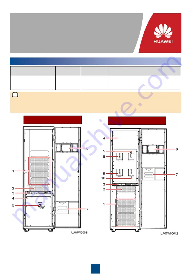
(1) Power units

(2) Bypass unit

(3) Control unit

(4) Power distribution 
subrack cover

(5) Maintenance bypass switch

(6) Monitor display unit (MDU)

(7) Folder

(8) Bypass input switch

(9) Main input switch

(10) Output switch

The UPS5000-A-200K-ST is a standard configuration model. The UPS5000-A-200K-FT is a full 
configuration model. A UPS in standard configuration has no mains input switch, bypass input 
switch, or output switch.

NOTE

Summary of Contents for UPS5000-A-200 Series

Page 1: ...0 mm UPS5000 A 200K FT UPS5000 A 200K ST UPS5000 A 200K FT 1 Power units 2 Bypass unit 3 Control unit 4 Power distribution subrack cover 5 Maintenance bypass switch 6 Monitor display unit MDU 7 Folder 8 Bypass input switch 9 Main input switch 10 Output switch The UPS5000 A 200K ST is a standard configuration model The UPS5000 A 200K FT is a full configuration model A UPS in standard configuration ...

Page 2: ...our rubber plugs from the bottom of the cabinet two on the front and two at the back 7 Insert four M12x115 expansion bolts into the expansion bolt holes in the floor and tighten the expansion bolts Secured Installation 1 Before installation read the user manual carefully to get familiar with product information and safety precautions 2 Use insulated tools during installation and operation 3 Only H...

Page 3: ...inside Cable scraps may ignite and cause personal injury or device damage After cables have been installed clean the cabinets in a timely manner Keep the cabinets and surrounding environment clean and tidy You need to prepare terminals onsite The stripped length of the copper wire should be the same as that of the part of the terminal that covers the conductor The cabling route is for reference on...

Page 4: ...ver from the power distribution subrack The cover can be opened only if the maintenance bypass switch is OFF NOTE 3 2 3 Remove the copper bars between mains input terminals and bypass input terminals 4 Connect the ground cable to the UPS In the preceding figure circled wiring terminals are primary ones and must connect to the ground cable NOTE ...

Page 5: ...Connect the battery cable Route a neutral wire from the middle of the positive and negative battery strings Take a battery string consisting of 40 batteries as an example A neutral wire is routed from the middle of positive and negative battery strings each consisting of 20 batteries NOTE ...

Page 6: ...n mains input terminals and bypass input terminals 3 Remove the cable cover for signal cables and remove small covers from the bottom based on site requirements 4 Connect power cables For the screw specifications and torque used for connecting cables in a bottom cable routing scenario refer to the top cable routing scenario This section only shows the cable routes in the bottom cable routing scena...

Page 7: ...bles from the Top 1 Remove a certain number of small covers from the top of the cabinet based on site conditions 4 Connect the ground cable to the UPS 3 Remove the copper bars between mains input terminals and bypass input terminals Connecting Cables to the UPS5000 A 200K FT 3 3 ...

Page 8: ...cable Route a neutral wire from the middle of the positive and negative battery strings Take a battery string consisting of 40 batteries as an example A neutral wire is routed from the middle of positive and negative battery strings each consisting of 20 batteries NOTE 8 Connect the output power cable ...

Page 9: ...talled on the left of the UPS cabinet refer to the user manual 1 Optional Determine the installation position for the cable entry cabinet and draw mounting holes in the installation position based on drawings 2 Remove the right and rear covers from the UPS cabinet and remove the front and rear covers from the cable entry cabinet Put away the removed screws and covers 3 Adjust the anchor bolts of t...

Page 10: ...onditions 10 Remove the signal cable trough cover from the cable entry cabinet 11 Connect signal cables The figure shows the signal cable routing and is for reference only Connect the cable based on the actual situation NOTE If the cable entry cabinet is placed on the left of the UPS cabinet remove the cable trough for signal cables and install it on the right of the cable entry cabinet NOTE ...

Page 11: ...nario This section only shows the cable routes in the bottom cable routing scenario NOTE NOTE For the cable connection method for the TN C system see the user manual Verifying the Installation 4 Verifying the Installation 1 Cabinet top 2 Wiring terminal blocks 3 Switches 4 Cabinet rear Positions to be checked 1 Check that there is no foreign matter in the cabinet ...

Page 12: ... input switches Full configuration model Close the UPS bypass input switch output switch and mains input switch After the UPS is powered on initialization begins The MDU displays the Huawei logo and an initialization progress bar Sealing putty Sealing putty must be used as a whole and the gap can be sealed only from the top Paper protective film 1 Before powering on the UPS ensure that the UPS has...

Page 13: ...tartup set the language time date network parameters and system parameters on the Settings Wizard screen b After you set parameters on the Settings Wizard screen the MDU displays the Bypass mode and No battery alarms which do not need to be handled If there is any other alarm you need to rectify the fault c View the system running status diagram on the MDU to check that the UPS is working in bypas...

Page 14: ...Power on password activation on the screen A message is displayed indicating whether to start the UPS Tap OK Enter Bar code and Verification code obtained from the MDU on the Offline Activation screen Tap Generate PWD to generate a startup password On the MDU choose System Info Maintenance Inv ON and obtain the Bar code and Verification Enter the generated password in the password textbox on the M...

Page 15: ...from the MDU 2 After confirming that the battery strings are properly connected turn on the battery string input circuit breaker If there are multiple battery strings turn on the circuit breaker for each battery string and then turn on the general circuit breaker between battery strings and the UPS The No battery alarm disappears from the MDU 3 Turn on the UPS downstream output switch to supply po...

Page 16: ... China www huawei com Scan here for more documents You can also log in to Huawei technical support website http support huawei com enterprise http support huawei com Support Support E WeChat Scan here for technical support enterprise Scan here for technical support carrier Huawei App Store Huawei App Store ...

Reviews: