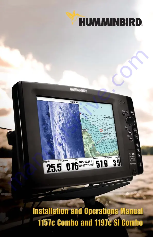
background image

Summary of Contents for 1157c Combo CHO

Page 1: ......

Page 2: ......

Page 3: ...e performed by authorized service personnel Any modification of the serial number or attempt to repair the original equipment or accessories by unauthorized individuals will void the warranty WARNING...

Page 4: ...ead Power Cable to the Boat 16 Transducer Installation Overview 18 1197c SI Transducer Installation 1197c SI Combo models only 18 1157c Transducer Installation 1157c Combo models only 25 Trolling Moto...

Page 5: ...ws and Readouts 65 Side Imaging View 1197c SI Combo models only 66 Sonar View 69 Sonar Zoom View 71 Split Sonar View 72 Side Sonar Combo View 1197c SI Combo models only 73 Snapshot and Recording View...

Page 6: ...ss Menu 110 Active Side 111 Split Position 111 Sensitivity 112 Upper Range Advanced Sonar Split Sonar and Active Sonar Side Views only 113 Lower Range 113 Chart Speed 114 Quad Layout with optional pur...

Page 7: ...D Card only 127 Delete Image optional purchase MMC SD Card Snapshot and Recording View only 127 Delete All Images optional purchase MMC SD Card Snapshot and Recording View only 128 Delete Recording op...

Page 8: ...ckpoint Interval 143 Track Min Distance Advanced 144 Track Color Range 144 Map Datum Advanced 144 Course Projection Line 145 3D View Outline 145 Export All Nav Data 145 Delete All Nav Data Advanced 14...

Page 9: ...ly 159 User Mode 159 Language International only 159 Triplog Reset with Speed input only 159 Restore Defaults 160 Select Readouts Advanced 160 Select Nav Readouts Advanced 163 Depth Offset Advanced 16...

Page 10: ...mplate XHS 9 HDSI 180 T 189 Contact Humminbird 190 NOTE Entries in this Table of Contents which list International only are only available on products sold outside of the U S by our authorized interna...

Page 11: ...ctly below the transducer Your 1100 Series Fishing System sends a sound wave signal and determines distance by measuring the time between the transmission of the sound wave and when the sound wave is...

Page 12: ...good balance between depth performance and resolution Low frequencies 83 kHz are typically used to achieve greater depth capability The power output is the amount of energy generated by the sonar tran...

Page 13: ...ch side and the depth capability are limited as compared to the 455 kHz frequency See What s on the Side Imaging Display and Understanding Side Imaging for more information DualBeam PLUS Sonar Your 11...

Page 14: ...System also supports GPS and chartplotting and uses GPS and sonar to determine your position display it on a grid and provide detailed underwater information The Global Positioning System GPS is a sa...

Page 15: ...nternational NVB models Your unit also comes with a built in UniMap with a detailed map of North America Domestic models or a detailed map of Europe and Southeast Asia including Australia and New Zeal...

Page 16: ...n accessory is plugged into the unit In addition multiple accessories can be attached simultaneously See Accessories Menu Tab and 1100 Series Accessories in this manual as well as your accessory Opera...

Page 17: ...allation process NOTE Installation procedures will depend on product configuration Power Temp Speed Temperature GPS Receiver WeatherSense Transducer 1 2 3 6 7 8 Speed through water Video Out 4 Optiona...

Page 18: ...the cable insulation Basic installation tasks that you must perform include Installing the Transducer Installing the control head choosing either gimbal or in dash mounting Installing the GPS Receiver...

Page 19: ...he knob and washer into the housing Tighten the gimbal knob to secure the 1100 Series control head to the mount Repeat step 2 for the other side You can now place the control head in various locations...

Page 20: ...NOTE Alternate hole patterns are available on the gimbal mounting bracket and may match existing holes on the boat You may choose to use one of these alternate hole patterns 4 Place the gimbal bracket...

Page 21: ...ing surface aligned with the drilled holes and fill the mounting holes with marine grade silicone sealant Insert the four 10 Slotted Hex wood screws into the mounting holes Hand tighten only 8 If the...

Page 22: ...don t have a cable for every hole in the insert install the blank plugs to protect the control head from the weather 11 Line up the cable collector insert and cover with the keying feature then slide...

Page 23: ...revent reverse installation so be careful not to force the connectors into the wrong sockets Adjust the control head to the desired viewing angle and secure by tightening the gimbal knobs NOTE You may...

Page 24: ...e paper In Dash Mounting template to the desired in dash mounting location 3 At a location inside the dotted line on the template drill a hole large enough to insert blade of reciprocating saw In addi...

Page 25: ...ttach the cable collector insert to the cable collector cover using the 2 6 Phillips screws provided 10 Plug the assembled cable collector into the back of the control head pushing gently but steadily...

Page 26: ...ogether and create a cleaner assembly NOTE It is very important that the cable collector is used and secured in place in the In Dash installation The Humminbird 1100 Series control head is now ready f...

Page 27: ...arate power source such as a second battery may be necessary 1a If a fuse terminal is available use crimp on type electrical connectors not included that match the terminal on the fuse panel Attach th...

Page 28: ...best to start with a smaller bit and use progressively larger drill bits to reduce the chance of chipping or flaking the outer coating NOTE Due to the wide variety of hulls only general instructions...

Page 29: ...ause of a stepped hull or cavitation noise trolling motor installation may be an option See Trolling Motor Transducer Installation for more information 1 First determine the best location on the trans...

Page 30: ...d be considered see Trolling Motor Transducer Installation The Side Imaging transducer must NOT have anything obstructing the view of the side looking beams i e nothing can be in the line of sight of...

Page 31: ...e between the pivot and the knuckle The square nuts will be prevented from rotating by the pocket in the back of the pivot An Allen wrench is provided which fits all the 1 4 20 screws but do not fully...

Page 32: ...sary to re tighten the pivot bolt after initial use as the plastic may still be conforming to the pressure from the lock washers 3 Adjust the height of the assembly so the face of the transducer is 1...

Page 33: ...d by the rotation of the transducer 2a If you are routing the cable over the transom of the boat secure the cable by attaching the cable clamp to the transom drilling 9 64 diameter holes for 8 x 5 8 w...

Page 34: ...the unit and that the transducer is fully submerged since the sonar signal cannot pass through air 4 If the unit is working properly gradually increase the boat speed to test high speed performance If...

Page 35: ...glasses and dust mask and marine grade silicone sealant NOTE Due to the wide variety of hulls only general instructions are presented in this installation guide Each boat hull represents a unique set...

Page 36: ...e or counter clockwise This turbulent water is normally confined to areas immediately aft of ribs strakes or rows of rivets on the bottom of the boat and in the immediate area of the propeller s Clock...

Page 37: ...rise adjustment NOTE If you cannot find a transom mount location that will work for your high speed application find an In Hull Transducer by contacting our Customer Resource Center at either 1 800 63...

Page 38: ...nting In this procedure you will assemble the transducer using the hardware provided then mount it and make adjustments to its position without locking it in place NOTE You will initially assemble the...

Page 39: ...one continuous line on the assembly NOTE The ratchets are keyed make sure that the square teeth on each ratchet face the square teeth on the transducer knuckle and the triangular teeth face outward H...

Page 40: ...assembly with the drilled holes in the transom With a 5 16 socket driver mount the assembly to the transom using the two 10 1 long screws provided NOTE Make sure that the mounting screws are snug but...

Page 41: ...he correct position on the transom by tracing the silhouette of the transducer mounting bracket with a pencil or marker 10 Tighten the pivot bolt using the pivot screw and nut to lock the assembly Han...

Page 42: ...you are routing the cable over the transom of the boat secure the cable by attaching the cable clamp to the transom drilling 9 64 diameter holes for 8 x 5 8 wood screws then skip directly to procedur...

Page 43: ...t the unit is working properly Make sure that the boat is in water greater than 2 but less than the depth capability of the unit and that the transducer is fully submerged since the sonar signal canno...

Page 44: ...ird mounting hole using a 5 32 drill bit Use a marine grade silicone sealant to fill all three drilled mounting holes especially if the holes penetrated the transom wall NOTE On fiberglass hulls it is...

Page 45: ...r marker Unscrew and remove the mounting screws and the transducer assembly and set aside 2 Drill the fourth mounting hole using a 9 64 drill bit Use a marine grade silicone sealant to fill all four d...

Page 46: ...r want to consider purchasing a Temperature Speed accessory a Temp Sensor or obtaining a different transducer Humminbird offers a transducer exchange program to swap the NEW and UNASSEMBLED transducer...

Page 47: ...transducer into the control head then power up the control head When the control head detects a functioning transducer it will automatically enter Normal operating mode 2 View the sonar signal at its...

Page 48: ...equired test the transducer in water at the desired depth If the performane is acceptable move on to Step 7 If the performance is not acceptable repeat Steps 3 through 6 7 Once you have determined the...

Page 49: ...the boat NOTE Proper operation requires the end of the transducer that has the mounting knuckle to face towards the bow of the boat 7 Weight the transducer so that it will not move while the epoxy is...

Page 50: ...ll the Humminbird Customer Resource Center at 1 800 633 1468 for details and pricing or visit www humminbird com for more information GPS Receiver Installation To optimize performance of the GPS recei...

Page 51: ...exceed 50 16 m NOTE Remember to seal screw holes and drilled holes as needed with marine grade silicone sealant to protect your boat from water damage 2 Screw on the receiver base to the stem first ma...

Page 52: ...r Make sure the receiver is flush on the surface and mark the two mounting holes with a pencil or punch 4 Move the receiver to the side and drill two pilot holes using a 9 64 3 5 mm bit NOTE Remember...

Page 53: ...eiver to the control head If holes are required to route the cable they must be 3 4 19 mm to allow for the cable connector Secure the NMEA cable with electrical tape NOTE Remember to seal screw holes...

Page 54: ...re the cable along its path to the control head as needed with cable ties 2 Plug the GPS receiver cable into the Communications port on the control head See Testing the System Installation to use the...

Page 55: ...ever menu mode happens to be highlighted and you will have to start again 2 Self Test displays results from the internal diagnostic self test including unit serial number Printed Circuit Board PCB ser...

Page 56: ...llows you to control what you see on the color display Refer to the following illustration and see Key Functions Views and The Menu System for more information Screen ZOOM Keys 4 WAY Cursor Control Ke...

Page 57: ...System by pressing the POWER LIGHT key The Title screen is displayed until the Fishing System begins operation Your 1100 Series will begin Normal or Simulator operation depending on the presence or ab...

Page 58: ...color spectrum indicating low to high sonar intensity returns where red indicates high intensity and white indicates low intensity RTS Real Time Sonar Window Thermoclines layers of water with differe...

Page 59: ...49 boat including the following items 7 8 10 3 4 5 6 9...

Page 60: ...t side of the display in the Sonar View only The RTS Window always updates at the fastest rate possible for depth conditions and shows only the returns from the bottom structure and fish that are with...

Page 61: ...or sand appears as a thicker line across the display Rocky Bottoms have a broken random appearance NOTE A sloping bottom will be represented as a thicker line across the display Harder bottoms typica...

Page 62: ...WhiteLine highlights the strongest sonar returns in white resulting in a distinctive outline This has the benefit of clearly defining the bottom on the display 52...

Page 63: ...a The information is scrolled down the screen as new data drawn at the top of the screen becomes available The side beams can be operated at one of two frequencies 455 kHz or 800 kHz Selecting 800 kHz...

Page 64: ...an keep a triplog of nautical or statute miles traveled Course the current direction the boat is traveling measured in degrees from North Voltage Bottom Return Topography Changes The water column show...

Page 65: ...position determines the intensity of the their relative density Upward slopes that face the transducer reflect sonar better than downward slopes Imaging display that allow for accurate interpretation...

Page 66: ...performance of 150 feet when the side beam frequency selection is set for 455 kHz The main benefit of Side Imaging sonar to anglers is that it provides an overall survey of a large area of water This...

Page 67: ...by straight line navigation and minimal side to side boat motion i e wave induced etc This applies to navigation by either the main engine or the trolling motor Minimize turning time and avoid wave ac...

Page 68: ...Submerged Bridge 1 Submerged Bridge Alternative Perspective 1 Submerged Timber 1 Submerged Tree 2 Submerged Ravine with Timber Submerged Ravine 3 Possible Drop Off 4 4 3 1 2 58...

Page 69: ...Swimming Pool 1 Submerged Swimming Pool 1 Bait Fish 1 Submerged Standing and Fallen Timber Plus Bait Fish Standing and Fallen Timber 2 1 2 59...

Page 70: ...Dumped Logs 1 Submerged Barge with Dumped Logs Submerged Barge 2 1 2 60...

Page 71: ...modes you can select on power up To adjust the backlight or to adjust the display background color press the POWER LIGHT key to access the Light and Background menu Use the 4 WAY Cursor key to select...

Page 72: ...use the DOWN or UP key to select the menu item and the LEFT or RIGHT key to alter a menu setting 4 WAY Cursor Control Key The 4 WAY Cursor Control Key has multiple functions depending on the situatio...

Page 73: ...order If Freeze Frame is active pressing EXIT will return to a scrolling display If the Cursor is active pressing EXIT will remove the cursor from the display Pressing Exit will also remove any displa...

Page 74: ...hat waypoint If the Cursor is not active pressing the GOTO key displays the list of waypoints so that you can select the waypoint towards which you want to navigate If the GOTO key is pressed and held...

Page 75: ...is displayed the readouts displayed depend on the view and whether you are navigating see Setup Menu Tab Select Readouts for more information Side Imaging View 1197c SI Combo models only Sonar View So...

Page 76: ...tail the range of the side beams the scrolling speed of the chart and the color scheme of the display all from the Side Imaging X Press Menu See Side Imaging X Press Menu as well as Understanding Side...

Page 77: ...Freeze Frame will zoom the Side Imaging Image around the cursor allowing for a more detailed inspection of the sonar returns Pressing EXIT will exit Freeze Frame and the display will start to scroll N...

Page 78: ...g measured in degrees from North 12 VLT Voltage 13 Full Range View 14 15 Side Imaging View with Active Cursor and Zoom 9 10 11 12 Cursor Info Box 1 Depth of Cursor 2 Depth Below Cursor 3 Distance to C...

Page 79: ...Sonar View and a cursor and cursor dialog box will be displayed on the screen The cursor can be positioned on the display using the 4 WAY Cursor Control key to determine the depth of any sonar return...

Page 80: ...curately receive continuous data Cursor Info Box Depth Lines 1 Depth of Cursor 2 Depth Below Cursor 3 Distance to Cursor 4 Bearing to Cursor 5 9 Active Cursor Icon 10 Depth 11 Temp Water Surface Tempe...

Page 81: ...and can be changed to suit conditions Upper and Lower Zoom Depth Range numbers indicate the depth of the water which is being viewed Freeze Frame Pressing any arrow on the 4 WAY Cursor Control key wil...

Page 82: ...a cursor and cursor dialog box will be displayed on the screen The cursor can be positioned on the display using the 4 WAY Cursor Control key to determine the depth of any sonar return In addition se...

Page 83: ...on for more information In this view you can change which side you look at the sensitivity of the sonar to allow you to see more or less the range of the side beams the scrolling speed of the chart an...

Page 84: ...een faster than MMC cards do Screen Snapshot When Screen Snapshot is enabled from the Accessories menu tab pressing the MARK key creates a saved screen capture when you have an optional purchase MMC S...

Page 85: ...by the camera icon NOTE You must have an MMC SD card installed to store or view waypoint thumbnails If you press the INFO key while the cursor is on a snapshot waypoint and the MMC SD card is missing...

Page 86: ...uring the recorded time period You can also use the X Press menu to change playback speed stop playback and delete recording icons Working with sonar recordings is a six step process 1 Displaying the...

Page 87: ...data will be shown and the Snapshot and Recording View will display the playback status You can change the speed skip to the beginning or end of playback and even reverse playback using the Playback...

Page 88: ...tion is cancelled when playback begins or ends You can delete the highlighted recording or all recordings using Delete Recording or Delete All Recordings from the Snapshot and Recording X Press menu N...

Page 89: ...llowing three layouts Default Classic and Slanted Default layout The top portion of the display presents a historical log of sonar returns from the 200 kHz down looking sonar beam New information in t...

Page 90: ...ng sonar beams New information appears at the top and scrolls down the display Water Surface Line for 455 kHz Sonar History Windows 8 200 kHz Sonar History Window 9 Upper Depth Range 10 Lower Depth Ra...

Page 91: ...left and right of the area shown in the down looking portion so you actually see more of the bottom The distance covered by the right and left beams is based on the depth setting for the down looking...

Page 92: ...moves the eye point forward and pressing the DOWN arrow key moves the eye point backward Pressing the EXIT key moves the eye point back to its original position behind and above the boat NOTE Only th...

Page 93: ...asured in degrees from North 5 Bearing Direction to Destination Waypoint measured in degrees from North 6 Boat Icon 7 Route 8 Off Course Limits 9 Cartography 10 Bird s Eye View Navigating Speed the me...

Page 94: ...left side of a split screen see Navigation X Press Menu Split Position for more information NOTE See Bird s Eye Views and Chart Views for more information about each side of this view NOTE Only the st...

Page 95: ...estination Waypoint measured in degrees from North 6 Chart Window 7 Cartography 8 3D View Outline 9 Boat Icon 10 Course Projection Line 11 Map Scale 12 Route 13 Bird s Eye Window 14 Chart Bird s Eye C...

Page 96: ...other area You can use the ZOOM keys to zoom in and out You can use the INFO key to get information on the chart objects near the cursor as well as to view Screen Snapshots Decluttered Waypoints Small...

Page 97: ...e Projection Line 13 Active Cursor 14 Declutter icons 15 Temp Water Surface Temperature 6 Speed Speed of Boat 7 Course the current direction the boat is traveling measured in degrees from North 8 VLT...

Page 98: ...tination Waypoint measured in degrees from North 6 Track 7 Declutter Icons 8 Boat Icon 9 Course Projection Line 10 Route 11 Waypoint 12 Cartography 13 Map Scale 14 Chart View Navigating with optional...

Page 99: ...u Active Side for more information A green arrow points to the side that is active You can also adjust the size of the left side of a split screen see Navigation X Press Menu Split Position for more i...

Page 100: ...ection to Destination Waypoint measured in degrees from North 6 Cartography 7 Off Course Limits 8 Track 9 Boat Icon 10 Course Projection Line 11 Route 12 Map Scale 13 14 Chart Chart Combo View Navigat...

Page 101: ...is active You can also adjust the size of the left side of a split screen see Sonar X Press Menu Split Position or Navigation X Press Menu Split Position for more information NOTE See Sonar View and C...

Page 102: ...so adjust the size of the left side of a split screen see Navigation X Press Menu Split Position or Side Imaging X Press Menu Split Position for more information NOTE See Side Imaging View and Chart V...

Page 103: ...various keys Panning Use the 4 WAY Cursor keys to move the chart around on the display in the direction of the key being pressed When you do this a Bullseye Cursor is drawn at the top of the screen an...

Page 104: ...est Port The position and services information for the nearest port to your present position will be displayed Press the EXIT key to remove the information box and the Bullseye Cursor will be centered...

Page 105: ...points Your 1100 Series can store up to 3000 waypoints XTE Cross Track Error Distance of Boat from Route 3 Depth 2 Next Waypoint 1 Course the current direction the boat is traveling measured in degree...

Page 106: ...sonar reading was taken The new waypoint will also record the depth at that location NOTE When you save a waypoint by any of these methods a numerical waypoint name is automatically assigned You can...

Page 107: ...which you want to navigate Press the GOTO key Navigation will begin immediately Navigate to a specified waypoint Press the GOTO key then choose the waypoint to which you would like to navigate from t...

Page 108: ...tance ranges from the targeted waypoint To remove the target choose Remove Target from the Navigation X Press Menu NOTE Only one waypoint can have either a target or a grid at one time If you apply a...

Page 109: ...one waypoint can have either a target or a grid at one time If you apply a target or a grid to a new waypoint the original waypoint will lose its target or grid NOTE The spacing of the rings on the wa...

Page 110: ...the RIGHT Cursor key again before the route is deleted Travel a saved route From the Routes submenu select Travel and press the RIGHT Cursor key A list of saved routes will appear Select the route yo...

Page 111: ...the track you want to hide or display and use the Cursor keys to select Hidden or Visible Press the EXIT key to return to the Tracks submenu Man Overboard MOB Navigation As soon as you know that you...

Page 112: ...key but does not remove any saved routes from memory MOB Navigation 1 2 3 4 Depth 1 XTE Cross Track Error Distance of Boat from Route 2 Speed speed of boat 3 Course the current direction the boat is t...

Page 113: ...e when you press the MENU key as well as whether you are in Normal or Advanced User Mode Either the Navigation or Screen Snapshot X Press Menu will appear depending on the view you are in Main Menu Ta...

Page 114: ...ll be at the same main menu tab you were on when you last displayed the main menu Total Screen Update When you change any menu settings that affect the view you are in the view will update immediately...

Page 115: ...Setup Tab Normal User Mode Setup Tab Advanced User Mode 105...

Page 116: ...wing paragraphs for more information about each of these choices Normal Operation Use Normal Operation for on the water operation Turn on your Fishing System by pressing the POWER LIGHT key The Title...

Page 117: ...NU key and then select Simulator manually to enter Simulator mode Manually selecting Simulator from the Start Up Options menu allows you to pre configure your Fishing System for on the water operation...

Page 118: ...ber software revision total hours of operation and the input voltage IP and MAC addresses are also displayed Accessory Test Accessory Test lists the accessories connected to the system NOTE The speed...

Page 119: ...ing monitored but is not yet being used This view also reports the current position local time and date and other numeric information The current GPS Fix Type is reported as No Fix 2D Fix 3D Fix or En...

Page 120: ...e in any of the Sonar Views to access the Sonar X Press Menu NOTE Menu choices will vary depending on system settings such as whether the unit is set for Advanced User mode NOTE Quad Layout only appea...

Page 121: ...key to change which side is active Left Right Default Left or Sonar Split Position Split Position allows you to adjust what percentage of the screen is taken up by the left side of any Combo View each...

Page 122: ...returns that may be of interest Decreasing the sensitivity eliminates the clutter from the display that is sometimes present in murky or muddy water If Sensitivity is adjusted too low the display may...

Page 123: ...together to view a specific depth range manually when looking for fish or bottom structure will be displayed in the lower right corner of the screen when you start manually adjusting the Lower Range t...

Page 124: ...ult 5 Quad Layout with optional purchase QuadraBeam PLUS Transducer Side Beam View only Quad Layout selects the method used to represent the sonar information from the two side looking beams plus the...

Page 125: ...ress menu choice will be displayed 10 60 feet or 3 20 meters International Models only Default 15 ft 5m Sonar Colors Sonar Colors allows you to select which color palette you would like to use for the...

Page 126: ...dels only Side Imaging Views only The Side Imaging X Press Menu provides access to the settings most frequently used Press the MENU key once while in any of the Sonar Views to access the Side Imaging...

Page 127: ...what percentage of the screen is taken up by the left side of any Combo View each view may be adjusted independently you must be in a specific view to adjust the screen size for that view The number...

Page 128: ...in the Side Imaging views The range must be set manually The SI Range menu choice can only be accessed from the Side Imaging Views To adjust the SI Range 1 From any Side Imaging View highlight SI Ran...

Page 129: ...ct which color palette you would like to use for the display To change the SI Colors 1 Highlight SI Colors on the Side Imaging X Press menu 2 Use the LEFT or RIGHT 4 WAY Cursor Control keys to change...

Page 130: ...he Chart Sonar Combo Chart Chart Combo View or Chart Bird s Eye Combo View to access the Navigation X Press Menu NOTE Menu choices will vary depending on system settings such as whether you are curren...

Page 131: ...ew to adjust the screen size for that view The number setting indicates the percentage taken up by the left side of the Combo View selecting Left sets the left side of the screen to its smallest setti...

Page 132: ...y if you have saved waypoints To move cursor to a saved waypoint 1 Highlight Cursor to Waypoint on the Navigation X Press menu 2 Use the RIGHT 4 WAY Cursor Control key to initiate Cursor to Waypoint 3...

Page 133: ...g a route To Save Current Route 1 Highlight Save Current Route on the Navigation X Press Menu 2 Use the RIGHT 4 WAY Cursor Control key to initiate saving the current route 3 The Confirm dialog box wil...

Page 134: ...ion removes the Man Overboard MOB waypoint and exits Man Overboard mode This menu choice will only appear when you are currently navigating in Man Overboard mode To Cancel MOB Navigation 1 Highlight C...

Page 135: ...sor to the desired position and press the MARK key once to save a waypoint 2 Highlight Waypoint Name on the Navigation X Press menu 3 Use the RIGHT 4 Way Cursor Control key to view the Waypoints subme...

Page 136: ...X Press menu provides access to the image management and sonar recording functions Press the MENU key once while in the Snapshot and Recording View to access the Snapshot and Recording X Press menu NO...

Page 137: ...ed To stop sonar recording 1 To stop recording highlight Stop Recording from any X Press menu 2 Press the RIGHT 4 Way Cursor key Delete Image optional purchase MMC SD Card Snapshot and Recording View...

Page 138: ...ard installed you are in Snapshot and Recording View To delete a recording 1 On the Snapshot and Recording View use the UP and DOWN 4 Way Cursor keys to highlight the recording you want to delete 2 Hi...

Page 139: ...layback Speed submenu choices which are represented by icons Beginning Rewind2 Rewind Reverse Normal Reverse Slow Pause Slow Play Normal Play FF FF2 End NOTE You can also change playback speed in the...

Page 140: ...the Main Menu System and then press the RIGHT Cursor key to select the Sonar tab NOTE Menu choices will vary depending on system settings such as whether the unit is set for Advanced User mode or wha...

Page 141: ...2 Use the LEFT or RIGHT 4 WAY Cursor Control keys to select either the 200 kHz beam the 83 kHz beam or the 200 83 kHz beam 200 83 kHz 200 kHz 83 kHz Default 200 kHz Side View Frequency 1197c SI Combo...

Page 142: ...o turn the Fish ID setting On or Off Off On Default Off Fish ID Sensitivity Fish ID Sensitivity adjusts the threshold of the Fish ID detection algorithms Selecting a higher setting allows weaker retur...

Page 143: ...splays returns that are within the transducer beam See Getting Started Using Your 1100 Series Real Time Sonar RTS Window for more information To change the RTS Window setting 1 Highlight RTS Window on...

Page 144: ...the width of the Zoomed Sonar the left hand side of the screen To change the Zoom Width 1 Highlight Zoom Width on the Sonar Main menu 2 Use the LEFT or RIGHT 4 WAY Cursor Control keys to change the w...

Page 145: ...in the Side Beam View The 455 kHz sensitivity can be adjusted without affecting the sensitivity of the 200 kHz returns shown in the 200 kHz sonar window To change the 455 kHz Sensitivity setting 1 Ma...

Page 146: ...ise Filter adjusts the sonar Noise Filter to limit interference on the display from sources such as your boat engine turbulence or other sonar devices The Noise Filter menu choice is available when Us...

Page 147: ...ge to 150 feet your 1100 Series will acquire bottom readings from 150 feet see Side Imaging X Press Menu SI Range To change the Max Depth setting 1 Make sure you are in Advanced User Mode then highlig...

Page 148: ...he LEFT or RIGHT 4 WAY Cursor Control keys to change the transducer selected 1197c Hi Def Sidescan Compact Sidescan Sidescan Quad Beam Dual Beam Dual 50 200 Universal Sonar 2 Default Hi Def Sidescan 1...

Page 149: ...igation Menu Tab Press the MENU key twice to access the Main Menu System then press the RIGHT cursor key to select the Navigation tab NOTE Menu choices will vary depending on system settings Navigatio...

Page 150: ...fferent depths on the track instead from light green shallowest to black deepest You can change the depth range associated with black by using Track Color Range menu setting see Navigation Main Menu T...

Page 151: ...changed Edit allows you to choose from a list of previously saved waypoints then edit the Name Position Latitude and Longitude and select the Icon that will be used to represent the waypoint in the Ch...

Page 152: ...a previously saved route to use as the current route this menu setting also begins navigation on this route Routes can be traveled in either the forward or reverse direction Info displays information...

Page 153: ...sor Control keys to change the Trolling Grid Rotation setting 0 to 89 Default 0 Trackpoint Interval Trackpoint Interval allows you to select the time period between trackpoints The current track can o...

Page 154: ...values will allow you to increase the track resolution Track Color Range Track Color Range allows you to set the depth range that will be displayed as black the deepest depth when Color By Depth is se...

Page 155: ...1 Highlight 3D View Outline on the Navigation main menu 2 Use the LEFT or RIGHT 4 WAY Cursor Control keys to change the 3D View Outline setting Hidden Visible Default Visible Export All Nav Data Expor...

Page 156: ...ver Override allows you to set which GPS receiver to use if you have multiple GPS receivers plugged in to your system These multiple GPS receivers may either be internal external or connected via the...

Page 157: ...key twice to access the Main Menu System and then press the RIGHT Cursor key to select the Chart tab NOTE Menu choices will vary depending on system settings such as whether the unit is set for Advan...

Page 158: ...ion To change the Chart Detail Level setting 1 Highlight Chart Detail Level on the Chart main menu 2 Use the LEFT or RIGHT 4 WAY Cursor Control keys to change the Chart Detail Level setting Basic Navi...

Page 159: ...s setting Hidden Visible Default Hidden Navaids on Bird s Eye View Navaids on Bird s Eye View allows you to display or hide additional navigational aids such as lights and buoys in Bird s Eye View NOT...

Page 160: ...ain menu 2 Use the LEFT or RIGHT 4 WAY Cursor Control keys to select which chart to use Default Auto Set Simulation Position Advanced Set Simulation Position allows you to set the position of the boat...

Page 161: ...then highlight Set Map Offset on the Chart main menu 3 Use the RIGHT 4 WAY Cursor Control key to set the Map Offset A confirmation dialog box will appear to allow you to change your mind or to confir...

Page 162: ...he Main Menu System The Alarms tab will be the default selection NOTE When an alarm is triggered you can silence it by pressing any key The alarm will be silenced and will not be triggered again until...

Page 163: ...Y Cursor Control keys to change the Depth Alarm setting OFF 1 to 100 feet or 0 5 to 30 meters International models only Default OFF Fish ID Alarm Fish ID Alarm sounds when the 1100 Series detects fish...

Page 164: ...onal purchase temp probe or Temp Speed only Aux Temp Alarm sounds when the water temperature from the Paddlewheel Temperature Probe detected by the Fishing System reaches the Aux Temp Alarm setting wh...

Page 165: ...nal models only Default 300 ft 100 m Arrival Alarm Arrival Alarm sounds when the boat has either exceeded the distance to the destination waypoint or has entered the Arrival Alarm Circle based on the...

Page 166: ...the boat s anchored position if the anchored boat drifts outside of that perimeter the Drift Alarm will sound To change the Drift Alarm setting 1 Highlight Drift Alarm on the Alarms main menu 2 Use t...

Page 167: ...tabbed Main Menu System then press the RIGHT cursor key until the Setup tab is selected NOTE Menu choices will vary depending on system settings such as whether the unit is set for Advanced User mode...

Page 168: ...t is Meters for International models and Feet for Domestic models Units Temp International only Units Temp selects the units of measure for all temperature related readouts International models only T...

Page 169: ...EFT or RIGHT 4 WAY Cursor Control keys to change the User Mode setting Normal Advanced Default Advanced Language International only Language selects the display language for menus International models...

Page 170: ...een or whether a particular readout will be turned off displaying nothing in that area Readout positions can also display information from supported accessories such as Temp Speed Data windows can dis...

Page 171: ...epth of the water Off Suppresses the readout so that no data shows in that position Position Position is the current location latitude longitude determined by GPS Speed Speed is the measurement of the...

Page 172: ...enu 2 Use the RIGHT 4 WAY Cursor Control key to initiate this procedure 3 The Select Readouts submenu will appear showing a list of all Readouts Use the UP or DOWN Cursor keys to select a particular R...

Page 173: ...ther way for non navigation mode using Select Readouts Non navigation readouts are automatically replaced on the display when navigating However Navigating readouts can have any type of information in...

Page 174: ...optional purchase Temperature Probe or Temp Speed accessory Time The current time Time Date The current time and date Triplog Displays the triplog which measures the elapsed time since last reset the...

Page 175: ...ux Temp Offset will adjust the aux temperature readout the temperature on the optional purchase temperature probe or Temp Speed accessory by the amount entered This menu choice is available only when...

Page 176: ...This menu choice is available only when in Advanced User Mode see Setup Menu Tab User Mode To change the Local Time Zone 1 Make sure you are in Advanced User Mode then highlight Local Time Zone on th...

Page 177: ...e time of day displayed when Time Date is selected as a Digital Readout see Navigation X Press Select Readouts To change the Time Format 1 Make sure you are in Advanced User Mode then highlight Time F...

Page 178: ...show numbers rounded to whole numbers NMEA Output Advanced NMEA Output turns the NMEA output on or off This menu choice is available only when in Advanced User Mode see Setup Menu Tab User Mode The fo...

Page 179: ...ntrol keys to change the Sonar to On or Off Off On Default On Video Out Video Out allows you to set the video format that will be sent to your remote monitor To use the Video Out feature 1 Highlight V...

Page 180: ...ny View 1 Highlight the View main menu tab 2 Use the UP or DOWN 4 WAY Cursor Control keys to select a View 3 Use the LEFT or RIGHT 4 WAY Cursor Control keys to change the status of the view from Hidde...

Page 181: ...shot menu choice If an accessory is attached however additional menu choices that support the accessory will be added automatically See the Operations Manual that comes with your accessory for detaile...

Page 182: ...Unavailable icon circle with a slanted line through it on the Snapshot and Recording View on the other unit To turn Screen Snapshot on or off 1 Highlight Screen Snapshot on the Accessories main menu 2...

Page 183: ...d slot 2 Press the VIEW key until you see the Chart View 3 Move the cursor until you are over a snapshot waypoint A thumbnail will be displayed within a frame and a line that points from the center of...

Page 184: ...ing corrosion from the battery terminals or wiring or actually replacing the battery if necessary 1100 Series Defaults to Simulator with a Transducer Attached A connected and functioning transducer wi...

Page 185: ...x of air and water flowing around the transducer cavitation may be interfering with the interpretation of sonar data See your Installation Guide for suggestions on adjusting the transducer position El...

Page 186: ...ears To determine whether the boat s engine is the source of the noise increase the RPMs while the boat is in neutral and stationary to see if the noise increases proportionately if noise appears when...

Page 187: ...BE THE CUSTOMER S EXCLUSIVE REMEDY EXCEPT FOR ANY APPLICABLE IMPLIED WARRANTIES UNDER STATE LAW WHICH ARE HEREBY LIMITED IN DURATION TO ONE YEAR FROM THE DATE OF ORIGINAL PURCHASE IN NO EVENT WILL HUM...

Page 188: ...r your e mail subject header You should include your Repair Authorization Number in all subsequent communications about your unit For IN WARRANTY service complete the following steps Obtain a Repair A...

Page 189: ...onar 2 features new temperature sensing and the performance of DualBeam PLUS technology available with all Humminbird DualBeam PLUS models An expanded view and greater bottom detail gives you a totall...

Page 190: ...nics to take responsibility for the management of waste from their products to achieve environmentally responsible disposal during the product life cycle WEEE compliance may not be required in your lo...

Page 191: ...ion moves across the display A faster setting displays sonar information from more pings and shows more detail but the information moves quickly across the display a slower setting permits viewing of...

Page 192: ...als are represented in progressively darker shades of gray While somewhat counter intuitive this method makes the sonar images crisper and has the benefit of enhancing the apparent sensitivity because...

Page 193: ...dth based on depth to optimize both target separation and depth performance See Target Separation QuadraBeam PLUS QuadraBeam PLUS is a Humminbird sonar configuration that uses four sonar beams for a m...

Page 194: ...for anglers using downriggers as it impacts the running depth of the down riggers Speed Over Ground is optimal for navigation as accurate destination times can be derived from this measurement Humminb...

Page 195: ...e reset to zero through the TripLog menu TrueArch TrueArch is a Humminbird feature that provides true fish arches not artificial arches or symbols Humminbird units are capable of producing fish arches...

Page 196: ...and will arrive at the destination in the most efficient manner COG is often confused with Heading See Heading Cross Track Error XTE Cross Track Error is the straight line distance of the boat from t...

Page 197: ...e GPS heading may vary from the boat compass heading because the compass uses Magnetic North Humminbird GPS units provide the option of selecting True or Magnetic readouts by using the North Reference...

Page 198: ...area Trolling Grid resolution be changed by zooming in or out on the chart The Trolling Grid can also be rotated on the display to orient it for optimal boat course for wave and wind conditions UTC UT...

Page 199: ...189 Appendix A Transducer Mounting Template XHS 9 HDSI 180 T Drill Drill Drill Use 5 32 drill bit TOP PLACE EITHER CORNER ON DEADRISE ANGLE Remove and use for Transducer Installation...

Page 200: ...ays By Telephone Monday Friday 8 00 a m to 4 30 p m Central Standard Time 1 800 633 1468 By e mail typically we respond to your e mail within three business days cservice johnsonoutdoors com For direc...

Reviews: