background image

Installation and Operations Manual

1158c Combo & 1198c SI Combo

Product Manual

Summary of Contents for 1158c Combo

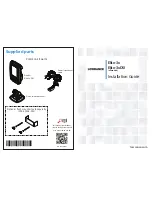
Page 1: ...Installation and Operations Manual 1158c Combo 1198c SI Combo Product Manual...

Page 2: ...ices to mariners contain all of the current information needed for the safety of navigation and the captain is responsible for their prudent use WARNING Disassembly and repair of this electronic unit...

Page 3: ...aps Premium Navionics Classic Charts and Platinum Cartography are trademarked by or registered trademarks of Navionics 1100 Series Cannon CannonLink Contour XD Down Imaging DualBeam PLUS Fish ID Hummi...

Page 4: ...Overview 19 1198c SI Transom Mount Transducer Installation Side Imaging Transducer XHS 9 HDSI 180T 1198c SI only 20 Overview Side Imaging Transducer XHS 9 HDSI 180T 1198c SI only 21 1158c Transom Moun...

Page 5: ...Software 58 Export Navigation Data 59 What s on the Sonar Display 60 Understanding the Sonar Display 62 Real Time Sonar RTS Window 62 SwitchFire 63 Freeze Frame and Active Cursor 63 Instant Image Upda...

Page 6: ...ide Imaging Combo View 1198c SI only 107 Chart Down Imaging Combo View 1198c SI only 108 Down Imaging Sonar Combo View 1198c SI only 109 Down Imaging Side Imaging Sonar Combo View 1198c SI only 110 Ch...

Page 7: ...nar Zoom View only when Bottom Lock is On 140 Cancel Navigation only when Navigating 140 Side Imaging X Press Menu Side Imaging Views only 1198c SI 141 Active Side Combo Views only 142 Split Position...

Page 8: ...ording optional purchase SD Card Snapshot and Recording View only 155 Stop Recording optional purchase SD Card only 155 Delete Image optional purchase SD Card Snapshot and Recording View only 155 Dele...

Page 9: ...h Lines Advanced 169 SI Range Lines Advanced Side Imaging View only 170 Noise Filter Advanced 170 Max Depth Advanced 171 Water Type Advanced 171 Transducer Select 172 Color Bar 172 Temperature Graph S...

Page 10: ...onal purchase Navionics charts only 184 NVB Chart Preference 184 Contour Lines optional purchase LakeMaster charts only 185 Depth Colors optional purchase LakeMaster charts only 185 Depth Highlight op...

Page 11: ...mat Advanced International only 195 Date Format Advanced International only 195 Digits Format Advanced 195 NMEA Output Advanced 196 Sonar 196 Demonstration 196 Video Out 196 Views Menu Tab 197 Accesso...

Page 12: ...horized international distributors To obtain a list of authorized international distributors please visit our Web site at humminbird com or contact our Customer Resource Center at 334 687 6613 NOTE En...

Page 13: ...ucer Your 1100 Series Fishing System sends a sound wave signal and determines distance by measuring the time between the transmission of the sound wave and when the sound wave is reflected off of an o...

Page 14: ...lance between depth performance and resolution Low frequencies 83 kHz are typically used to achieve greater depth capability The power output is the amount of energy generated by the sonar transmitter...

Page 15: ...bility are limited as compared to the 455 kHz frequency See What s on the Side Imaging Display and Understanding the Side Imaging Display for more information DualBeam PLUS Sonar 1158c 1198c SI Your 1...

Page 16: ...where to put your bait by showing if fish are to the left right or directly beneath your boat Universal Sonar 2 Your 1100 Series Fishing System supports Universal Sonar 2 a state of the art integrate...

Page 17: ...however civilians may also take advantage of its highly accurate position capabilities typically within 4 5 meters depending on conditions This means that 95 of the time the GPS receiver will read a l...

Page 18: ...ration the menu options that correspond with the connected accessory will be added to the menu system Please read all instructions that are relevant for your configuration before beginning the install...

Page 19: ...or contact our Customer Resource Center at 1 800 633 1468 NOTE Accessories connected to the RS 232 or Video Out connectors require a separate power source Ethernet Connector Your unit has a built in...

Page 20: ...ng System additional functions will be added to the menu system automatically See Accessories Menu Tab and Fishing System Accessories in this manual Also see the accessory s operations manual for addi...

Page 21: ...te purchase You can visit our Web site at humminbird com to order these accessories online or contact our Customer Resource Center at 1 800 633 1468 Control Head Installation You have two choices for...

Page 22: ...it is best to start with a smaller bit and use progressively larger drill bits to reduce the chance of chipping or flaking the outer coating Fill all holes with marine grade silicone sealant NOTE You...

Page 23: ...drill a 1 25 mm hole that will allow you to run the cables close to the bracket Pass the cables through the 1 25 mm hole routing the cables through the grommet and pressing the grommet into place Plac...

Page 24: ...the cables pass through the slots on the hole cover and that there is enough cable slack to allow for the control head to pivot through its full tilt range Extra cable slack will also help when conne...

Page 25: ...ews provided 13 Place the control head back onto the mounting bracket Plug the assembled cable collector into the back of the control head pushing gently but steadily until you feel the collector snap...

Page 26: ...ish to dress the cabling with nylon wire ties in order to hold the cables together and create a cleaner assembly Plugging the Assembled Cable Connector into the Back of the Control Head Installation G...

Page 27: ...area of the dash to mount the control head The control head requires a depth of at least 4 inches 102 mm 2 Tape the paper In Dash Mounting template to the desired in dash mounting location 3 At a loc...

Page 28: ...ent reverse installation so be careful not to force the connectors into the wrong slots If you don t have a cable for every hole in the insert install the blank plugs to protect the control head from...

Page 29: ...s and cable sockets are keyed to prevent reverse installation so be careful not to force the connectors into the wrong sockets NOTE You may wish to dress the cabling with nylon wire ties in order to h...

Page 30: ...er source such as a second battery may be necessary 1a If a fuse terminal is available use crimp on type electrical connectors not included that match the terminal on the fuse panel Attach the black w...

Page 31: ...guide Each boat hull represents a unique set of requirements that should be evaluated prior to installation It is important to read the instructions completely and understand the mounting guidelines...

Page 32: ...es the transducer safe distance from the motor and turbulence The Side Imaging has a clear view side to side Obstructed View The transducer is too close to motor turbulence and the Side Imaging view i...

Page 33: ...are several procedures you will have to perform in order to install a transom mounted transducer They are as follows Determine transducer mounting location Mount the bracket to the boat Attach the piv...

Page 34: ...er s The best way to locate turbulence free water is to view the transom while the boat is moving This method is recommended if maximum high speed operation is a high priority If this is not possible...

Page 35: ...right corner of the template 3 Using a pencil or punch mark the three mounting holes on the transom Do not mark or drill any other holes at this time 4 Using a 5 32 4 0 mm bit drill the three holes t...

Page 36: ...e pivot 2 Insert the headed pin through the pivot holes in the bracket and pivot The headed pin can be inserted from either side of the bracket 3 Place the nylon washer over the opposite end of the he...

Page 37: ...hree mounting screws 4 In order to gain access to the mounting screws the transducer assembly must be pivoted up in the bracket as shown Be careful not to alter the running angle as some force is nece...

Page 38: ...edure 5 Connecting the Cable or 2b If you will be routing the cable through a hole in the transom drill a 5 8 diameter hole above the waterline Route the cable through this hole then fill the hole wit...

Page 39: ...that the transducer is fully submerged since the sonar signal cannot pass through air 4 If the unit is working properly gradually increase the boat speed to test high speed performance If the unit fu...

Page 40: ...cedures in this section There are several procedures you will have to perform in order to install a transom mounted transducer They are as follows Locate the transducer mounting location Prepare the m...

Page 41: ...lockwise This turbulent water is normally confined to areas immediately aft of ribs strakes or rows of rivets on the bottom of the boat and in the immediate area of the propeller s Clockwise propeller...

Page 42: ...ransducer allows it to point straight down without deadrise adjustment NOTE If you cannot find a transom mount location that will work for your high speed application find an In Hull Transducer by con...

Page 43: ...he transom of the boat and use a pencil or marker to mark where to drill the two mounting holes Mark the drill holes near the top of each slot making sure that your mark is centered in the slot 4 Make...

Page 44: ...a ruler measure the distance from the bottom of the plumb line to the back of the transom then use the chart NOTE It is important to take your measurement in the figure showing Measuring the Transom...

Page 45: ...until it snaps into place with the other hand Refer to the illustration Transducer Knuckle Positions Ratchets Placed in Position 1 Ratchets Placed in Position 2 Fitting the Pivot Arm Over the Ratchet...

Page 46: ...gently pry the assembly away from the mounting bracket 4 Align the mounting bracket transducer assembly with the drilled holes in the transom With a 5 16 socket driver mount the assembly to the transo...

Page 47: ...rt to starboard horizontally level as you look at the transducer from behind the boat 9 Mark the correct position on the transom by tracing the silhouette of the transducer mounting bracket with a pen...

Page 48: ...enough slack in the cable for this movement It is best to route the cable to the side of the transducer so the transducer will not damage the cable during movement 2a If you are routing the cable over...

Page 49: ...control head and the transom transducer and have routed all the cables you must perform a final test before locking the transducer in place Testing should be performed with the boat in the water alth...

Page 50: ...d speeds you are ready to lock down the transducer settings Force the pivot to the Up position to gain access to the mounting screws then re align the mounting bracket against the transom of the boat...

Page 51: ...ew and remove the mounting screws and the transducer assembly and set aside 2 Drill the fourth mounting hole using a 9 64 drill bit Use a marine grade silicone sealant to fill all four drilled mountin...

Page 52: ...rchasing a Temperature Speed accessory a Temp Sensor or obtaining a different transducer Humminbird offers a transducer exchange program to swap the NEW and UNASSEMBLED transducer accompanied by mount...

Page 53: ...first that includes running the boat at various speeds in order to determine the best mounting area before permanently mounting the transducer 1 Plug the transducer into the control head then power u...

Page 54: ...e on to Step 6 Otherwise locate a new position in the hull and repeat Steps 3 through 5 6 Run the boat at various speeds and water depths while observing the screen on the control head If depth perfor...

Page 55: ...f the hull with epoxy 6 Press the transducer into place with a slight twisting motion to purge any trapped air from underneath keeping the end of the transducer that has the mounting knuckle pointed f...

Page 56: ...hase a Trolling Motor Adapter kit that will allow you to mount the transducer on the trolling motor You may also exchange your NEW and UNASSEMBLED transducer with mounting hardware included for a trol...

Page 57: ...r cutting of your boat surfaces If you have purchased hardware to stem mount your GPS receiver follow the instructions included with that hardware to mount the stem antenna pole NOTE AS EC10 10 extens...

Page 58: ...5 Attach the GPS receiver to its base using the included 6 7 8 screws 2b Access Under Mounting Location Follow these steps to deck mount the GPS receiver when routing the cable down through the mount...

Page 59: ...ble from Humminbird if your planned routing exceeds 20 6 m Maximum cable length including extensions should not exceed 50 16 m 2 Confirm the cable length is good and route the cable from the receiver...

Page 60: ...long its path to the control head as needed with cable ties 2 Plug the GPS receiver cable into the Communications port on the control head See Testing the System Installation to use the System Status...

Page 61: ...ault to whichever menu mode happens to be highlighted and you will have to start again 2 Self Test displays results from the internal diagnostic self test including unit serial number Printed Circuit...

Page 62: ...there isn t a transducer attached to the control head NOTE See Start Up Options Menu for more information If a functioning transducer is connected Normal operation will be selected automatically at po...

Page 63: ...see on the color display Refer to the following illustration and see Key Functions Views and The Menu System for more information Screen ZOOM Keys VIEW Key MARK Key GOTO Key EXIT Key 1 2 3 7 8 9 4 WA...

Page 64: ...tdown occurs properly and any menu settings will be saved your Fishing System should always be turned off using the POWER LIGHT key Adjust the Backlight or the Display Background Color Press the POWER...

Page 65: ...tting The changes will be activated and saved immediately Freeze Frame In Sonar View Side Imaging View and Down Imaging View press any arrow on the 4 WAY Cursor Control key to freeze the display and m...

Page 66: ...m From any view press the EXIT key to cycle through the available views in reverse order If Freeze Frame is active press the EXIT key to return to a scrolling display If the Cursor is active press the...

Page 67: ...ituation Active Cursor Press the GOTO key while in any view to create a waypoint and start navigation towards that waypoint Without Active Cursor Press the GOTO key to display the saved waypoints list...

Page 68: ...unit and insert the card into the slot Press down on the card until it clicks into place 3 Close the slot cover and turn the knob just 1 4 of a turn to close Do NOT overtighten as this will not impro...

Page 69: ...to Select When you install the SD card in your control head your Fishing System will retrieve the chart and display it automatically Chart Select You can also choose which chart to display with the Ch...

Page 70: ...count Set up a new account 3 Download From My Account My Profile My Equipment click the file name of the latest software update unit name version Read the instructions in the dialog box and click Down...

Page 71: ...ursor key The Confirm dialog box will appear To confirm export press the RIGHT Cursor key once more To cancel export press the LEFT Cursor key NOTE If an SD memory card is not installed an error messa...

Page 72: ...of water with different temperatures that appear at different depths and different times of the year A thermocline typically appears as a continuous band of many colors moving across the display at t...

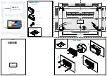
Page 73: ...61 to your boat including the following items What s on the Sonar Display 7 10 3 4 5 6 11...

Page 74: ...e Sonar RTS Window appears on the right side of the display in the Sonar View only The RTS Window always updates at the fastest rate possible for depth conditions and shows only the returns from the b...

Page 75: ...e Active Cursor Press any arrow on the 4 WAY Cursor Control key and the screen will freeze and a cursor will be displayed Use the 4 WAY Cursor Control key to move the cursor over a sonar return and th...

Page 76: ...or sand appears as a thicker line across the display Rocky Bottoms have a broken random appearance NOTE A sloping bottom will be represented as a thicker line across the display Harder bottoms typical...

Page 77: ...WhiteLine highlights the strongest sonar returns in white resulting in a distinctive outline This has the benefit of clearly defining the bottom on the display 65 What s on the Sonar Display...

Page 78: ...rain The dark part of the screen indicates soft bottom sand mud or descending terrain The water column shows the relative depth of the water under the boat at a given time Variations in the width of t...

Page 79: ...play that allow for accurate interpretation of bottom What s on the Side Imaging Display 7 3 4 5 6 8 10 12 9 Clouded Area May indicate a bait ball and White Streaks may indicate fish Boat Icon Top of...

Page 80: ...small strip of the bottom perpendicular to the direction of the boat Each time the unit pings a strip of data representing all the echoes received by the transducer are put together on the display to...

Page 81: ...esults are displayed in a picture like image on the screen Frequencies The side beams can be operated at one of two frequencies 455 kHz or 800 kHz Your Side Imaging transducer also provides DualBeam P...

Page 82: ...navigation by either the main engine or the trolling motor Minimize turning time and avoid wave action that induces large side to side rocking of the boat For example if there is a lot of wave activi...

Page 83: ...Submerged Tree 2 Submerged Ravine with Timber Submerged Ravine 3 Possible Drop Off 4 4 3 1 2 New Bridge Pilings 1 Creek Channel 2 Submerged Bridge Creek Channel and New Bridge Pilings Submerged Bridge...

Page 84: ...Bait Fish 1 Submerged Standing and Fallen Timber plus Bait Fish Standing and Fallen Timber 2 1 2 Submerged Bridge 1 Submerged Bridge Alternative Perspective 1 What s on the Side Imaging Display 72...

Page 85: ...Dumped Logs 1 Submerged Barge with Dumped Logs Submerged Barge 2 1 2 Swimming Pool 1 Submerged Swimming Pool 1 73 What s on the Side Imaging Display...

Page 86: ...When you press the EXIT key the display cycles through the available views in reverse order Customize You can display or hide any view to suit your fishing preferences See the following pages for more...

Page 87: ...omized 1 Press the MENU key twice to access the tabbed Main Menu then press the RIGHT Cursor key until the Setup tab is selected 2 Press the DOWN key to highlight Select Readouts or Select Nav Readout...

Page 88: ...the SI View will freeze and a cursor will appear on the screen Use the 4 WAY Cursor Control key to move the cursor over a sonar return and observe the following The depth of the sonar return you choo...

Page 89: ...0 10 Bottom Return 11 10 Boat Icon 12 10 Side Imaging View 1 2 3 4 Depth water depth 1 Temp water surface temperature 2 Speed speed of boat 3 Course the current direction the boat is traveling measure...

Page 90: ...easured in degrees from North 12 VLT Voltage 13 Full Range View 14 15 Side Imaging View with Active Cursor and Zoom 9 10 11 12 Cursor Info Box 1 Depth of Cursor 2 Depth Below Cursor 3 Distance to Curs...

Page 91: ...n Imaging X Press Menu You can set the sensitivity of the sonar to see more or less detail the chart scrolling speed and the display color palette see Down Imaging X Press Menu Freeze Frame Press any...

Page 92: ...ower Range 10 10 11 10 12 10 Down Imaging View 1 2 3 4 Depth water depth 1 Boat Position Latitude Longitude 2 Speed speed of boat 3 Course the current direction the boat is traveling measured in degre...

Page 93: ...measured in degrees from North 12 VLT Voltage 13 Full Range View 14 15 Down Imaging View with Active Cursor and Zoom 9 10 11 12 Cursor Info Box 1 Depth of Cursor 2 Depth Below Cursor 3 Distance to Cur...

Page 94: ...ottom visible on the display although you can adjust it manually as well see Sonar X Press Menu Digital Readouts shown on the display will change based on the Select Readouts settings or the optional...

Page 95: ...or for any other reason that the unit can t accurately receive continuous data Upper Depth Range Structure 1 Temperature Graph 2 Depth Lines 3 RTS Window 4 Sonar Color Bar 5 7 Depth 8 Temp Water Surfa...

Page 96: ...hanges the zoomed view updates automatically The Full Range View is displayed on the right side of the screen The Full Range View includes the Zoom Preview Box which shows where the zoomed view is in...

Page 97: ...wer Depth Range Full Range View 13 Sonar Zoom View 1 2 3 4 Depth 1 Temp water surface temperature 2 Speed speed of boat 3 Course the current direction the boat is traveling measured in degrees from No...

Page 98: ...tomized therefore information such as water temperature and voltage are unavailable in the Split Sonar View Freeze Frame Use the 4 WAY Cursor Control key to freeze the display and move the cursor over...

Page 99: ...ress the MENU key once in this view to open the X Press Menu Use the X Press Menu to Start Recording Delete Images or adjust the Recording and Playback settings see Recording and Playback or Snapshot...

Page 100: ...is saved A waypoint will also be created at the boat or active cursor location The screen snapshot shares the same file name PNG Delete a Screen Snapshot 1 From the Snapshot and Recording View press t...

Page 101: ...indicates that the view is a saved screen snapshot and not a live view If you press the INFO key and the snapshot file connected to the icon is not saved on the installed SD card the Chart Information...

Page 102: ...t the boat location and the recording shares the same file name SON Stop recording 1 In any view press the MENU key once to open the Snapshot and Recording X Press Menu 2 Highlight Stop Recording and...

Page 103: ...her speeds not every sonar return can be processed and displayed Stop Playback 1 Press the MENU key once to open the Snapshot and Recording X Press Menu 2 Highlight Stop Playback and press the RIGHT C...

Page 104: ...and move the Active Cursor to a location on the sonar view The Cursor dialog box will show the depth and information for the location you choose Press Exit to resume Playback Press the MARK key during...

Page 105: ...verage The sonar information from the side looking beams reveals bottom contour structure and fish similar to the down looking beam but the area covered is to the left and right which gives you a wide...

Page 106: ...r beams New information in the side beam panels scrolls from the center out 8 200 kHz Sonar History Window 9 Upper Depth Range 10 Lower Depth Range 11 Side Beam View Default Layout 1 2 3 4 Depth 1 Tem...

Page 107: ...sonar beams New information appears at the top and scrolls down the display Water Surface Line for 455 kHz Sonar History Windows 8 200 kHz Sonar History Window 9 Upper Depth Range 10 Lower Depth Range...

Page 108: ...and scrolls to the left Right Side 455 kHz Sonar History Window 8 Water Surface Line 9 Upper Depth Range 10 Lower Depth Range 11 Side Beam View Slanted Layout 1 2 3 4 Depth 1 Temp water surface tempe...

Page 109: ...eye point forward and press the DOWN Cursor key to move the eye point backward Press the EXIT key to move the eye point back to its original position behind and above the boat Digital Readouts If all...

Page 110: ...red in degrees from North 5 Bearing Direction to Destination Waypoint measured in degrees from North 6 Boat Icon 7 Route 8 Off Course Limits 9 Cartography 10 Bird s Eye View Navigating Speed the measu...

Page 111: ...OTE See Chart Menu tab and Navigation Menu tab for more information Shift Pan Use the 4 WAY Cursor Control key to shift pan the chart to another area Zoom Press the ZOOM keys to zoom in and out Inform...

Page 112: ...ion Line 13 Active Cursor 14 Decluttered Waypoint icons 15 Temp Water Surface Temperature 6 Speed Speed of Boat 7 Course the current direction the boat is traveling measured in degrees from North 8 VL...

Page 113: ...n arrow points to the active side Active Side Press the MENU key once and select Active Side from the X Press Menu Choose RIGHT or LEFT to set the active side X Press Menu After you set the Active Sid...

Page 114: ...the chart scrolling speed and the color scheme of the display For more information about each side of this combo view see Sonar View and Side Imaging View Side Sonar Combo View Side Imaging Range 9 B...

Page 115: ...ght For more information about each side of this combo view see Chart View and Bird s Eye View Chart Bird s Eye Combo View Standard 1 2 3 4 Depth 1 Temp water surface temperature 2 Speed speed of boat...

Page 116: ...ute 3 Depth 2 Next Waypoint 1 Course the current direction the boat is traveling measured in degrees from North 5 Bearing Direction to Destination Waypoint measured in degrees from North 6 Cartography...

Page 117: ...information about each side of this combo view see Chart View and Sonar View Chart Sonar Combo View 1 2 3 4 Depth 1 Temp water surface temperature 2 Speed speed of boat 3 Course the current direction...

Page 118: ...For more information about each side of this combo view see Chart View and Side Imaging View Chart Side Combo View 1 2 3 4 Depth 1 Temp water surface temperature 2 Speed speed of boat 3 Course the cu...

Page 119: ...each side of this combo view see Down Imaging View and Side Imaging View Down Imaging Side Imaging Combo View 1 2 3 4 Depth 1 Boat Position Latitude Longitude 2 Speed speed of boat 3 Course the curren...

Page 120: ...about each side of this combo view see Down Imaging View and Chart View Chart Down Imaging Combo View 1 2 3 4 Depth 1 Boat Position Latitude Longitude 2 Speed speed of boat 3 Course the current direct...

Page 121: ...of this combo view see Down Imaging View and Sonar View Down Imaging Sonar Combo View 1 2 3 4 Depth 1 Boat Position Latitude Longitude 2 Speed speed of boat 3 Course the current direction the boat is...

Page 122: ...appear in both the Sonar and Down Imaging views For more information about each side of this combo view see Down Imaging View Side Imaging View and Sonar View Down Imaging Side Imaging Sonar Combo Vi...

Page 123: ...n of motion always Up in the Course Up orientation Viewing Cartography In the Chart or Combo Views there are several cartography related functions that you can access using various keys Panning Use th...

Page 124: ...ress the EXIT key to remove the information box and the cursor bull s eye will be centered over the port position The cursor information boxes will indicate the distance and bearing to the port from y...

Page 125: ...the GOTO key A route represents your intended navigation and shows the shortest path from each waypoint to the next As you travel a route staying on the route line is the most efficient way to get to...

Page 126: ...l waypoints on the screen See Navigation Menu Tab Waypoint Decluttering to turn off this feature XTE Cross Track Error Distance of Boat from Route 3 Depth 2 Next Waypoint 1 Course the current directio...

Page 127: ...aypoints submenu Program a specific position as a waypoint To create a waypoint that is NOT your current position from the Waypoints submenu select Create and press the RIGHT Cursor key Use the 4 WAY...

Page 128: ...d Cancel navigation From the Navigation X Press Menu select Cancel Navigation and press the RIGHT Cursor key Canceling navigation removes the route and any waypoints created using the GOTO key but it...

Page 129: ...r key to display the saved waypoints list Select a waypoint and press the RIGHT Cursor key The grid can also be rotated to any heading by adjusting the Grid Rotation setting on the Navigation Menu Tab...

Page 130: ...Speed speed of boat 3 Course the current direction the boat is traveling measured in degrees from North 4 VLT Voltage 5 Cartography 6 5 Waypoint Target 7 Targeted Waypoint 8 Course Projection Line 9...

Page 131: ...ed speed of boat 3 Course the current direction the boat is traveling measured in degrees from North 4 VLT Voltage 5 Cartography 6 5 Waypoint Trolling Grid 7 Waypoint for Grid 8 Course Projection Line...

Page 132: ...the Routes submenu select Delete and press the RIGHT Cursor key Select the route you want to delete and press the RIGHT Cursor key You will be asked to confirm your choice by pressing the RIGHT Curso...

Page 133: ...nu select Edit and press the RIGHT Cursor key to display the saved tracks list Select the track you want to edit and press the RIGHT Cursor key Delete a saved track From the Saved Tracks submenu selec...

Page 134: ...and the MOB View will show the following The view will switch to the Chart View and the elapsed time since MOB was activated will be displayed A line will be drawn from the boat s current position to...

Page 135: ...is traveling measured in degrees from North 4 Bearing Direction to Destination Waypoint measured in degrees from North 5 5 Position where Man Overboard was activated 6 Elapsed Time since MOB was activ...

Page 136: ...Press Menu The X Press Menu provides a shortcut to the most frequently used settings and the options on the X Press Menu correspond with the current view Main Menu The Main Menu is a standard set of m...

Page 137: ...Power On the Control Head for more information Normal Use Normal for on the water operation with a transducer connected If a functioning transducer is connected Normal operation will be selected auto...

Page 138: ...y in the same way as they would in Normal operation Any menu changes you make will be saved for later use A message will appear often on the display to indicate Simulator mode To exit Simulator power...

Page 139: ...lowing options Self Test Accessory Test GPS Diagnostic View To exit System Status power off your Fishfinder Self Test displays results from the internal diagnostic self test including unit serial numb...

Page 140: ...est lists the accessories connected to the system NOTE The speed accessory will be detected only if the paddlewheel has moved since your Fishfinder was powered up Accessory Test Screen Start Up Option...

Page 141: ...e and other numeric information The current GPS Fix Type is reported as No Fix 2D Fix 3D Fix or Enhanced An Enhanced fix has been augmented using information from WAAS EGNOS or MSAS A 3D or Enhanced F...

Page 142: ...r keys to change the menu setting NOTE The X Press Menu will collapse temporarily and the screen will update if it is affected by your menu setting change which allows you to see the effects of your c...

Page 143: ...ghlight a menu tab 3 Press the DOWN or UP Cursor keys to select a specific menu option under that tab 4 Press the RIGHT or LEFT Cursor keys again to change a menu setting A down arrow at the bottom of...

Page 144: ...ation If you press MENU or EXIT to leave the Main Menu and then return to the Main Menu at a later time the menu will open to the same tab as the last time the Main Menu was displayed Note for all Men...

Page 145: ...r Mode setting 1 Press the MENU key twice to access the Main Menu 2 Press the RIGHT Cursor key until the Setup tab is selected 3 Press the DOWN Cursor key to highlight User Mode on the Setup main menu...

Page 146: ...Sonar Tab Normal Mode Sonar Tab Advanced Mode Menu Quick Tips 134...

Page 147: ...the Sonar Views to access the Sonar X Press Menu NOTE Menu options can be expanded or simplified by setting the User Mode to Advanced or Normal See Main Menu User Mode for details NOTE Quad Layout onl...

Page 148: ...active side When a menu is displayed in the active side the non active side of the screen will be grayed out Split Position Combo Views only Settings Left 30 40 50 60 70 Right Default Various Split Po...

Page 149: ...ensitivity is adjusted too low the display may not show many sonar returns that could be fish When operating in very clear water or greater depths increase the sensitivity to see weaker returns that m...

Page 150: ...of the screen to indicate the unit is in Manual mode Adjust the Upper and Lower Range together to view a specific depth range especially when looking for fish or bottom structure NOTE A minimum dista...

Page 151: ...fault Quad Layout allows you to choose how sonar information is displayed in the Side Beam View The Side Beam View displays sonar data from the left and right 455 kHz beams as well as the 200 kHz down...

Page 152: ...eturn Choose a larger value to see large structure in deeper water NOTE It is possible to set the Bottom Range to be greater than the depth In this case you may see surface clutter in a wavy band that...

Page 153: ...ost frequently used settings Press the MENU key once while in any of the Side Imaging Views to access the Side Imaging X Press Menu NOTE Menu options can be expanded or simplified by setting the User...

Page 154: ...r setting indicates the percentage taken up by the left side of the Combo View Selecting Left sets the left side of the screen to its smallest setting SI Side Settings Left Both Right Default Both SI...

Page 155: ...Sensitivity can be adjusted from the SI Enhance dialog box or the Side Imaging X Press Menu The Sensitivity setting is provided here so that you can easily adjust the Side Imaging data with the other...

Page 156: ...rmation on the display longer which allows you to see an entire area SI Colors Settings Blue Amber1 Amber2 Brown Green Inverse Gray Green Red Default Blue SI Colors allows you to select which color pa...

Page 157: ...ost frequently used settings Press the MENU key once while in any of the Down Imaging Views to access the Down Imaging X Press Menu NOTE Menu options can be expanded or simplified by setting the User...

Page 158: ...w is on the screen see Views Combo Views The number setting indicates the percentage taken up by the left side of the Combo View Selecting Left sets the left side of the screen to its smallest setting...

Page 159: ...t is in Manual mode Adjust the Upper and Lower Range together to view a specific depth range especially when looking for fish or bottom structure NOTE A minimum distance of 10 feet will be maintained...

Page 160: ...d like to use for the Side Imaging and Down Imaging display Down Imaging Beam Width Advanced Down Imaging View only Settings Narrow Medium Wide Default Wide Down Imaging Beam Width controls the width...

Page 161: ...Eye View Chart Views or Chart Combo Views to access the Navigation X Press Menu NOTE Menu choices will vary depending on system settings such as whether you are currently navigating NOTE To see the Na...

Page 162: ...ercentage taken up by the left side of the Combo View Selecting Left sets the left side of the screen to its smallest setting Waypoint Name Only with an active cursor on a waypoint Settings Edit Delet...

Page 163: ...ursor key and follow screen instructions Clear Current Track allows you to clear the current track on the display and start a new track at the present position Save Current Route only when Navigating...

Page 164: ...appear when you are currently navigating in Man Overboard mode Remove Target only if a Target is Active Settings Press the RIGHT Cursor key to activate Remove Target removes the waypoint target from t...

Page 165: ...llowing menu options Edit allows you to edit the Name Position Latitude and Longitude and select the Icon that will be used to represent the waypoint in the Chart and Combo Views Delete allows you to...

Page 166: ...s access to the snapshot management and sonar recording functions Press the MENU key once while in the Snapshot and Recording View to access the Snapshot and Recording X Press Menu NOTE For more infor...

Page 167: ...allows you to delete a single screen capture image This menu option is only available when an optional purchase SD card is installed Snapshot and Recording View is on the screen and you have selected...

Page 168: ...ck Auto is the default setting for Pings Per Second and automatically adjusts the ping rate for best recording quality If there is limited memory on your SD card you can slow the ping rate by setting...

Page 169: ...age since at higher speeds not every sonar return can be processed Stop Playback optional purchase SD Card only Settings Press the RIGHT Cursor key to activate Stop Playback allows you to stop playbac...

Page 170: ...Menu System The Alarms tab will be the default selection NOTE When an alarm is triggered you can silence it by pressing any key The alarm will be silenced and will not be triggered again until a new i...

Page 171: ...pth becomes equal to or less than the menu setting Fish ID Alarm Settings Off All Large Medium Large Default Off Fish ID Alarm sounds when the Fishfinder detects fish that correspond to the alarm sett...

Page 172: ...ture Probe detected by the Fishing System reaches the Aux Temp Alarm setting which is set in degrees Fahrenheit or Celsius International Models only Temp Alarm Settings Off 33 120 Fahrenheit 0 50 Cels...

Page 173: ...s Off 25 to 3000 ft 10 to 1000 m International Models only Default 150 ft 50 m Arrival Alarm sounds when the boat has either exceeded the distance to the destination waypoint or has entered the Arriva...

Page 174: ...ational Models only Default Off Drift Alarm allows you to set the size of a perimeter around the boat s anchored position If the anchored boat drifts outside of that perimeter the Drift Alarm will sou...

Page 175: ...r tab is selected NOTE Menu options can be expanded or simplified by setting the User Mode to Advanced or Normal See Main Menu User Mode for details NOTE The Sonar Menu Tab will change to display menu...

Page 176: ...ow beam will be displayed in the Sonar View The Split Sonar View will continue to display returns from both beams in their respective windows The RTS Window in the Sonar View will display the returns...

Page 177: ...ly raw sonar returns on the display When Max Mode is selected you will see the maximum sonar information available within the transducer beam so more fish arches and better jig tracking are shown Choo...

Page 178: ...cer beam angle the distance to a fish decreases as the fish moves into the beam and then increases as it moves out again creating a Fish Arch when this distance change is shown on the display Boat spe...

Page 179: ...urns it off in the Sonar View The RTS Window always updates at the fastest rate possible and only displays returns that are within the transducer beam See What s on the Sonar Display for more informat...

Page 180: ...and structure on the display See What s on the Sonar Display Sonar Bottom Presentation for more information Zoom Width Sonar Zoom View only Settings Narrow Medium Wide Default Wide Zoom Width adjusts...

Page 181: ...o Advanced see Setup Menu Tab User Mode NOTE Visit our Web site at humminbird com to order this accessory online or contact our Customer Resource Center at 1 800 633 1468 Depth Lines Advanced Settings...

Page 182: ...vanced Settings Off Low Medium High1 High2 High3 Default Low Noise Filter adjusts the sonar Noise Filter to limit interference on the display from sources such as your boat engine turbulence or other...

Page 183: ...ur unit for operation in fresh or salt water In salt water you can also choose the shallow or deep setting Water Type affects the accuracy of deep water depth readings In salt water what would be cons...

Page 184: ...tion The Compact Sidescan Sidescan QuadraBeam Plus and other transducers require a separate purchase 1158c Dual Beam is the default selection The QuadraBeam PLUS Dual 50 200 kHz and Universal Sonar 2...

Page 185: ...formation shown on the display To see only the data directly under your boat select Narrow Medium reveals more information while Wide displays the maximum information available from the Down Imaging b...

Page 186: ...Navigation tab is selected NOTE Menu options will vary depending on system settings such as whether you are currently navigating NOTE Menu options can be expanded or simplified by setting the User Mo...

Page 187: ...black deepest You can change the depth range associated with black by using Track Color Range menu setting see Navigation Menu Tab Track Color Range Saved Tracks Settings Edit Delete Default Saved Tr...

Page 188: ...delete a waypoint from the saved waypoints list Cursor To allows you to move the cursor quickly to a waypoint from the saved waypoints list Go To allows you to select a waypoint and start navigation t...

Page 189: ...llows you to choose a route from the saved routes list and use it as your current route Routes can be traveled in either the forward or reverse direction When you select a route navigation begins imme...

Page 190: ...seconds Default 1 second Trackpoint Interval allows you to select the time period between trackpoints The current track can only contain up to 20 000 trackpoints so longer time periods cause the track...

Page 191: ...ow extending from the bow of the boat that projects your current course and shows where the boat will go if you continue on your present course 3D View Outline Settings Hidden Visible Default Visible...

Page 192: ...Internal External Auto Default Auto GPS Receiver Override allows you to set which GPS receiver to use if you have multiple GPS receivers plugged into the system These multiple GPS receivers may be in...

Page 193: ...User Mode to Advanced or Normal See Main Menu User Mode for details NOTE When a map from an optional purchase SD card is installed the Chart Menu Tab will change to display menu options that correspo...

Page 194: ...lot and select Left to use the SD card installed in the left card slot see SD Memory Card Slots Add Maps to Your Fishing System NOTE The SD Cards require a separate purchase For more information visit...

Page 195: ...ctivate Clear Map Offset allows you to clear the Map Offset The Clear Map Offset menu option is available when Map Offset is active Shaded Depth Settings Off 1 to 180 Feet or 1 to 60 Meters Internatio...

Page 196: ...al purchase Navionics charts only Settings Hidden Visible Default Hidden Spot Soundings allows you to display or hide spot soundings which are depth measurements shown on the chart NOTE Spot Soundings...

Page 197: ...epth Highlight Range optional purchase LakeMaster charts only Settings 0 60 ft 0 30 fathoms 0 20 m International Models only Default 5 ft 2m Depth Highlight Range adjusts the range on each side of the...

Page 198: ...Scroll Use the UP or DOWN Cursor keys to scroll through the list As each lake is highlighted you can view information about the lake in the white box displayed on the screen Cursor To Highlight a lak...

Page 199: ...nu then press the RIGHT Cursor key until the Setup tab is selected NOTE Menu options will vary depending on which accessories are attached to the unit NOTE Menu options can be expanded or simplified b...

Page 200: ...d input only Settings Domestic Models Statute Miles Nautical Miles Default Statute Miles International Models Meters Kilometers Meters Nautical Miles Feet Statute Miles Feet Nautical Miles Default Met...

Page 201: ...us Default English Language selects the display language for menus International Models only Triplog Reset with Speed input only Settings Press the RIGHT Cursor key and follow screen instructions to a...

Page 202: ...Speed accessory All views share the same set of 5 readouts that can be set one way for navigation mode using Select Nav Readouts and another way for non navigation mode using Select Readouts Non navig...

Page 203: ...arrive at the destination in the most efficient manner See the Glossary for more information Depth Displays the depth of the water Off Suppresses the readout so that no data shows in that position Po...

Page 204: ...d accessories such as Temp Speed All views share the same set of 5 readouts that can be set one way for navigation mode using Select Nav Readouts and another way for non navigation mode using Select R...

Page 205: ...ure Aux Temp The current detected water temperature from an optional purchase Temperature Probe or Temp Speed accessory Time The current time Time Date The current time and date Triplog Displays the t...

Page 206: ...readout by the amount entered Speed Calibration Advanced with Speed paddlewheel only Settings 20 to 20 Default 0 Speed Calibration will adjust the speed readout by the percentage entered and will app...

Page 207: ...Time Date is selected as a Digital Readout see Setup Menu Tab Select Readouts Date Format Advanced International only Settings mm dd yy dd mm yy yy mm dd Default mm dd yy Date Format changes the date...

Page 208: ...sentences are also output APB Autopilot Sentence B BWR Bearing and Distance to Waypoint RMB Recommended Minimum Navigation Info Sonar Settings Off On Default On Sonar deactivates Sonar and removes th...

Page 209: ...u tab allows you to set the available views to hidden or visible in the view rotation The view will be removed from the view rotation if it is set to Hidden and will be displayed in the view rotation...

Page 210: ...l head the menu choices that support the accessory will be added automatically See the Operations Manual that comes with your accessory for detailed information NOTE Accessories to enable WeatherSense...

Page 211: ...vailable icon circle with a slanted line through it on the Snapshot and Recording View on the other unit AIS optional purchase AIS equipment only Settings Press the RIGHT Cursor key to activate Your F...

Page 212: ...on the view and a new target messge is received the oldest target will disappear from the view MMSI Tag Maritime Mobile Service Identity will be displayed if it is available for each target Target Co...

Page 213: ...al miles TCPA sets the closest point of approach measured in time Target List shows active targets and related information that is available with each AIS update Press the RIGHT Cursor key to open the...

Page 214: ...AIS Target List Accessories Menu Tab 202...

Page 215: ...luding removing corrosion from the battery terminals or wiring or actually replacing the battery if necessary 1100 Series Defaults to Simulator with a Transducer Attached A connected and functioning t...

Page 216: ...and water flowing around the transducer cavitation may be interfering with the interpretation of sonar data See your Installation Guide for suggestions on adjusting the transducer position Electrical...

Page 217: ...noise re appears To determine whether the boat s engine is the source of the noise increase the RPMs while the boat is in neutral and stationary to see if the noise increases proportionately if noise...

Page 218: ...IES OBLIGATIONS OR LIABILITIES ON THE PART OF HUMMINBIRD AND WILL BE THE CUSTOMER S EXCLUSIVE REMEDY EXCEPT FOR ANY APPLICABLE IMPLIED WARRANTIES UNDER STATE LAW WHICH ARE HEREBY LIMITED IN DURATION T...

Page 219: ...tion Number for your unit NOTE Please do not return your Humminbird product to the store for service Please have your product model name and serial number available before calling the factory If you c...

Page 220: ...credit card number and expiration date money order or personal check Please do not send cash Tag product with your name street address phone number and your assigned Repair Authorization Number Includ...

Page 221: ...ht and out of harm s way with no clamps ties or exposed wires Universal Sonar 2 features new temperature sensing and the performance of DualBeam PLUS technology available with all Humminbird DualBeam...

Page 222: ...a PC in order to upload product software updates and new features obtained from humminbird com This accessory requires the MSWindows compatible HumminbirdPC software downloaded from our Web site to y...

Page 223: ...hermal layers bottom composition and slope ENVIRONMENTAL COMPLIANCE STATEMENT It is the intention of Humminbird to be a responsible corporate citizen operating in compliance with known and applicable...

Page 224: ...e as published by the Free Software Foundation either version 2 of the License or at your option any later version This program is distributed in the hope that it will be useful but WITHOUT ANY WARRAN...

Page 225: ...ed by black high contrast pixels All monochrome fixed mount Humminbird products use FSTN technology Frequency A measure of the number of sound wave cycles per second of a sound impulse transmitted und...

Page 226: ...water is constant and the time for the signal to return is measured Sound also travels very quickly underwater making sonar a responsive cost effective tool Sonar is the basic technology behind all r...

Page 227: ...so that objects of equal size i e fish appear to be the same size even if they are separated by a good distance Transducer The transducer is part of the sonar system which mounts on the boat and is in...

Page 228: ...astal United States and on some inland waterways These correction signals are provided by the USCG and received by an auxiliary Differential Beacon Receiver DBR that connects to the GPS receiver The a...

Page 229: ...D card is virtually identical in function to an MMC however the speed at which information can be accessed is generally faster the storage capacity is generally larger and the card has security featur...

Page 230: ...o GPS that provides enhanced accuracy through correction signals broadcast from Federal Aviation Administration WAAS satellites stationed over the USA These secondary signals are automatically receive...

Page 231: ...c file start with the following print settings Scale None Paper 8 5 x 11 inches Layout Portrait Confirm that the template matches the transducer bracket slots and adjust the print as needed Drill Dril...

Page 232: ...ys By Telephone Monday Friday 8 00 a m to 4 30 p m Central Standard Time 1 800 633 1468 By e mail typically we respond to your e mail within three business days service humminbird com For direct shipp...

Reviews: