
Summary of Contents for 200DX Dual Beam
Page 1: ......
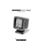
The Humminbird 200DX Dual Beam is a high-performance fish finder designed to enhance your fishing experience. To maximize its potential, you need the detailed Operation Manual. You can easily and conveniently download this manual for free from our website, ensuring you make the most of this incredible product.
Page 1: ......