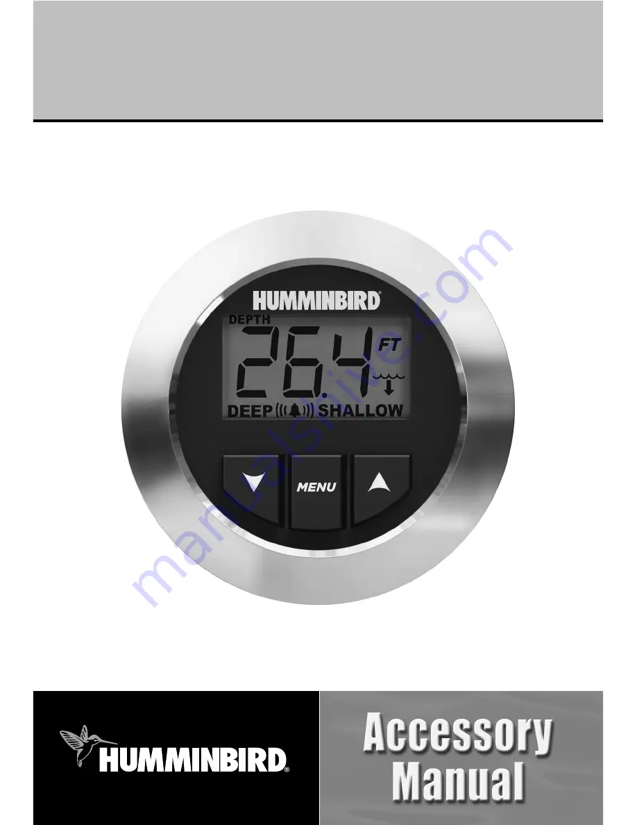
background image

531874-1_B

HDR 650 Installation

and Operations Manual

HDR 650 Installation

and Operations Manual

Summary of Contents for HDR 650

Page 1: ...531874 1_B HDR 650 Installation and Operations Manual HDR 650 Installation and Operations Manual ...

Page 2: ...b site at humminbird com WARNING This device should not be used as a navigational aid to prevent collision grounding boat damage or personal injury When the boat is moving water depth may change too quickly to allow time for you to react Always operate the boat at very slow speeds if you suspect shallow water or submerged objects WARNING Disassembly and repair of this electronic unit should only b...

Page 3: ... Transom Transducer Installation 10 1 Locating the Transducer Mounting Position 10 2 Preparing the Mounting Location 12 3 Assembling the Transducer and Initial Mounting 13 4 Routing the Cable 18 5 Connecting the Cable 20 6 Test and Finish the Installation 20 7 Locking Down the Transducer Optional 24 Inside the Hull Transducer Installation 25 1 Locating the Transducer Mounting Position 25 2 Trial I...

Page 4: ...6 HDR 650 Maintenance 36 Transducer Maintenance 36 Troubleshooting 37 HDR 650 Doesn t Power Up 37 No Bottom Reading on the Display 38 No Continuous Depth Display in Very Shallow Water 38 Screen Fades Images are Not Sharp 38 Bottom Reading Disappears During a Hard Turn 38 1 Year Limited Warranty 39 Humminbird Service Policy 40 Returning Your Unit for Service 41 Specifications 42 Contact Humminbird ...

Page 5: ...l as the user controls and display The transducer is mounted beneath the water surface and converts electrical energy from the transmitter into mechanical pulses or sound waves The transducer also receives the reflected sound waves and converts them back into electrical signals for display on the sonar unit Sonar is very fast A sound wave can travel from the surface to a depth of 240 ft 70 m and b...

Page 6: ...wered hand drill and various drill bits including a 2 1 8 hole saw if your boat does not have an existing gauge hole Phillips head and flat head screwdrivers ruler or measuring tape pen or pencil 12 Volt power source your boat s battery marine grade silicone sealant for sealing drilled holes two part slow cure epoxy for inside the hull transducer installation only NOTE If you are wiring directly t...

Page 7: ...test before operating your HDR 650 Perform the following high level steps by following the instructions in each numbered section to install the depth sounder 1 Locating the HRD 650 mounting position 2 Cutting the mounting hole 3 Customizing and assembling the HDR 650 4 Installing the HDR 650 5 Installing the buzzer 6 Connecting to the power supply 7 Installing the transducer 3 Installation ...

Page 8: ...protect the HDR 650 from excessive wave shock and vibration Allow at least 2 clearance at the back sides and top of the unit for connection air flow and ease of installation and removal 2 Cutting the Mounting Hole Once you have selected your mounting location perform the following steps 1 Mark the desired mounting location then drill a pilot hole 2 Drill a 2 1 8 diameter hole using a hole saw and ...

Page 9: ...rovide a lasting waterproof bond the face plate adhesive is extremely sticky and you will NOT be able to re position it once you have stuck it onto the face of the HDR 650 3 Carefully line up the face plate with the face of the HDR 650 Press the face plate into place so that all keys are accessible and the display is visible see illustration 4 Align the inside tabs of the trim ring with the HDR 65...

Page 10: ...e dashboard 2 From the rear of the dashboard install the gasket and collar onto the HDR see illustration 3 Hand tighten the collar until the HDR is securely mounted in the dashboard Make sure that the face of the HDR stays oriented upright Hand tightening the Collar Collar Gasket Dashboard View HDR 650 Control Head Attaching the Gasket and Collar 6 Installation ...

Page 11: ... a fuse panel in the console area that can be used to attach the HDR 650 power cable If a fuse terminal is available use crimp on type electrical connectors not included that match the terminal on the fuse panel Attach the black wire to ground and the red wire to 12 VDC power You must use a 1 Amp fuse in the connection 36 of power cable is included you may shorten or lengthen this cable using 18 g...

Page 12: ...e instructions carefully so that you may understand the installation requirements 1a If a fuse terminal is available use crimp on type electrical connectors not included that match the terminal on the fuse panel Attach the black wire to ground and the red wire to positive 12 VDC power Install a 1 amp fuse not included for protection of the unit Humminbird is not responsible for over voltage of ove...

Page 13: ...nting on the boat directly exposed to the water On fiberglass hull boats this same transducer can be bonded to the inside of the hull When mounted inside the hull the sonar signal actually passes through the hull of the boat One of these two mounting techniques will produce acceptable results on most boats There are however several situations that may demand a different type of transducer Inboard ...

Page 14: ...r clockwise or counter clockwise This turbulent water is normally confined to areas immediately aft of ribs strakes or rows of rivets on the bottom of the boat and in the immediate area of the propeller s Clockwise propellers create more turbulence on the port side On outboard or inboard outboard boats it is best to locate the transducer at least 15 to the side of the propeller s see the illustrat...

Page 15: ...ucer too close to trailer bunks or rollers to avoid moving or damaging the transducer during loading and unloading of the boat If high speed operation is critical you may want to consider using an In Hull transducer instead of this Transom Mount transducer NOTE The hydrodynamic shape of your transducer allows it to point straight down without deadrise adjustment NOTE If you cannot find a transom m...

Page 16: ...he illustration Boat Hull Types Require Different Mounting Positions NOTE If you have a flat bottomed aluminum boat some additional adjustment may be needed to accommodate the rivets on the bottom of the boat i e the gap may need to be a little smaller than 1 8 This will help you to avoid excessive turbulence at high speeds NOTE If your propeller moves clockwise in forward as you re facing the ste...

Page 17: ... will assemble the transducer using the hardware provided then mount it and make adjustments to its position without locking it in place NOTE You will initially assemble the transducer and the pivot arm by matching the two ratchets to a numbered position on the transducer knuckle Further adjustments may be necessary 1a If you already know your transom angle refer to the chart below for the initial...

Page 18: ...tchets at position 1 the beads on each ratchet will line up with the rib on the transducer knuckle to form one continuous line on the assembly see the illustration Ratchets Placed in Position 1 NOTE The ratchets are keyed make sure that the square teeth on each ratchet face the square teeth on the transducer knuckle and the triangular teeth face outward Hold the ratchets on the transducer knuckle ...

Page 19: ...ll need to access the mounting bracket in the next step NOTE If the pivot assembly is snapped closed over the mounting bracket use a flat head screwdriver or similar tool to gently pry the assembly away from the mounting bracket see the illustration Prying the Assembly Away from the Mounting Bracket Transducer Knuckle Positions Ratchets Placed in Position 1 Ratchets Placed in Position 2 Rib Fittin...

Page 20: ... Assembly to the Transom NOTE Make sure that the mounting screws are snug but do not fully tighten the mounting screws at this time to allow the transducer assembly to slide for adjustment purposes 5 Snap the pivot arm down into place Mounting the Assembly to the Transom Inserting the Pivot Arm Assembly Into the Mounting Bracket Prying the Assembly Away from the Mounting Bracket 16 Transom Mount T...

Page 21: ...ransducer Mounting Position NOTE The transducer has a natural downward slant of 4 5 degrees from leading edge closest to the boat transom to trailing edge farthest away from the boat Looking at the back of the transducer the seam should be slightly below the bottom of the hull 8 Continue to adjust until the bracket is also level from port to starboard horizontally level as you look at the transduc...

Page 22: ...ile connector which must be routed to the point where the control head is mounted There are several ways to route the transducer cable to the area where the control head is installed The most common procedure routes the cable through the transom into the boat NOTE Your boat may have a pre existing wiring channel or conduit that you can use for the transducer cable 1 Unplug the other end of the tra...

Page 23: ...ou are routing the cable over the transom of the boat secure the cable by attaching the cable clamp to the transom drilling 9 64 diameter holes for 8 x 5 8 wood screws then skip directly to procedure 5 Connecting the Cable or 2b If you will be routing the cable through a hole in the transom drill a 5 8 diameter hole above the waterline Route the cable through this hole then fill the hole with mari...

Page 24: ...ot to force the plug into the connector the wrong way 6 Test and Finish the Installation Once you have installed both the HDR 650 and the transom transducer and have routed all the cables you must perform a final test before locking the transducer in place Testing should be performed with the boat in the water although you can initially confirm basic operation with the boat out of the water 1 Turn...

Page 25: ...ments see the illustration Adjusting the Transducer Mounting Position NOTE The deeper the transducer is in the water the more likely that a rooster tail of spray will be generated at high speeds so make sure that the transducer is as high as it can be and still be submerged in the water If you are still not getting good high speed readings you may need to disassemble the transducer mounting assemb...

Page 26: ... the transducer settings Force the pivot to the Up position to gain access to the mounting screws then re align the mounting bracket against the transom of the boat to match the traced silhouette Check the bracket position with the level again to make sure it is still level then mark the third mounting hole using a pencil or marker Unscrew and remove the mounting screws and the transducer assembly...

Page 27: ...Re position the transducer assembly against the transom of the boat then hand install all three screws Make sure that the transducer location and the pivot angle have not changed then fully tighten all three mounting screws see the illustration Fully Tighten All Three Mounting Screws Snap the pivot back down If you have performed the preceding procedures correctly the transducer should be level an...

Page 28: ...remove the mounting screws and the transducer assembly and set aside 2 Drill the fourth mounting hole using a 9 64 drill bit Use a marine grade silicone sealant to fill all four drilled mounting holes especially if the holes penetrate the transom wall 3 Re position the transducer assembly against the transom of the boat then hand install the first three screws two on the outside edges and one in t...

Page 29: ...nsider the following to find the best location Observe the outside of the boat hull to find the areas that are mostly free from turbulent water Avoid ribs strakes and other protrusions as these create turbulence As a general rule the faster the boat can travel the further aft and closer to the centerline of the hull the transducer has to be located in order to remain in contact with the water at h...

Page 30: ...ransducer it will automatically enter Normal operating mode 2 View the sonar signal at its best by holding the transducer over the side immersed in the water so that it is pointing straight down over a known flat bottom Use the display to benchmark against the sonar signal that will be detected once the transducer is placed in the hull 3 Place the transducer body face down at the identified mounti...

Page 31: ...ed test the transducer in water at the desired depth If the performance is acceptable move on to Step 7 If the performance is not acceptable repeat Steps 3 through 6 7 Once you have determined the best mounting location using the above steps mark the position of the transducer 3 Routing the Cable 1 Once the mounting location is determined and you have marked the position of the transducer route th...

Page 32: ... of the transducer and the inside of the hull with epoxy see the illustration Coating the Transducer with Epoxy 5 Press the transducer into place with a slight twisting motion to purge any trapped air from underneath keeping the pointed end of the transducer body pointed forward towards the bow see the illustration Pressing the Transducer Into Place NOTE Proper operation requires the pointed end o...

Page 33: ...ns that are included with the bracket Trolling Motor Transducer Options If you don t have a trolling motor transducer there are several options You may purchase a Trolling Motor Adapter kit that will allow you to mount the transducer on the trolling motor You may also exchange your NEW and UNASSEMBLED transducer with mounting hardware included for a trolling motor transducer NOTE There are also se...

Page 34: ...play LCD offers sharp viewing even in bright direct sunlight and is continuously lit for nighttime operation NOTE Actual depth capability depends on such factors as bottom hardness water conditions and transducer installation Units will typically read to deeper depths in fresh water than in salt water The HDR 650 Control Head The HDR 650 uses a backlit display together with a 3 button keypad to co...

Page 35: ... Overview 1 Select a Function Press the MENU key repeatedly until you reach the appropriate menu 2 Adjust the Setting Press the UP or DOWN arrow key to adjust the setting Press Hold either key to scroll through the range of settings quickly 3 Save After your selection is made wait 5 seconds for the unit to return to normal operation Your settings are saved automatically even after the unit is powe...

Page 36: ...eters or fathoms 1 Press the MENU key until the Units icon is displayed and flashing on the screen 2 Press the UP or DOWN arrow key to scroll through the available units FT feet M meters FA fathoms 3 After your selection is made wait 5 seconds for the unit to return to normal operation Your settings are saved automatically Units Set 32 Operations ...

Page 37: ... or exceed the current Deep Alarm setting see the Deep Alarm section 3 After your selection is made wait 5 seconds for the unit to return to normal operation Your settings are saved automatically and the Shallow icon will be visible on the display 4 Alarm If the depth of the water is less than the saved setting the alarm will sound and the alarm icon will flash on the screen Mute Press any key to ...

Page 38: ...p below the current Shallow Alarm setting see the Shallow Alarm section 3 After your selection is made wait 5 seconds for the unit to return to normal operation Your settings are saved automatically and the Deep icon will be visible on the display 4 Alarm If the depth of the water is greater than the saved setting the alarm will sound and the alarm icon will flash on the screen Mute Press any key ...

Page 39: ...displayed and flashing on the screen 3 Enter your chosen offset measurement as follows Keel Press the DOWN arrow key to enter the measurement from step 1 as a negative number 1 to 10 feet 1 to 3 0 meters or 1 to 1 6 fathoms Default 0 Waterline Press the UP arrow key to enter the measurement from step 1 as a positive number 1 to 10 feet 1 to 3 0 meters or 1 to 1 6 fathoms Default 0 4 After your sel...

Page 40: ...r or trunk the extremely high temperatures generated in hot weather can damage the electronics Transducer Maintenance If your boat remains in the water for long periods of time algae and other marine growth can reduce the effectiveness of the transducer Periodically clean the face of the transducer with hot water Pivoting the transducer up in the bracket may allow better access for inspection or c...

Page 41: ... 650 doesn t power up refer to the Installation section and make sure that the power cable is properly connected to the HDR 650 the power cable is wired correctly with red to positive battery terminal and black to negative terminal or ground the fuse is operational a fuse can often appear to be good when in fact it is not check the fuse with a tester or replace it with a known good fuse if the uni...

Page 42: ...g adjusting the transducer or actually replacing the transducer cable if necessary No Continuous Depth Display in Very Shallow Water Losing continuous depth when the boat is in very shallow water is normal because the automatic range control cannot lock onto the bottom in depths of one foot or less Screen Fades Images are not Sharp If the screen begins to fade and images are not as sharp as normal...

Page 43: ... than that recommended in the product installation and operation instructions Damaged or has failed because of an accident or abnormal operation Repaired or modified by entities other than Humminbird Please retain your original receipt as a proof of the purchase date This will be required for in warranty service THIS WARRANTY IS EXPRESSLY IN LIEU OF ANY OTHER WARRANTIES OBLIGATIONS OR LIABILITIES ...

Page 44: ...will be assessed for each repair physical damage and missing parts are not included Any repairs made after the original warranty will be warranted for an additional 90 days after service has been performed by our factory technicians You can contact our Customer Resource Center or visit our web site to verify the flat rate repair fee for your product visit the Product Support section http www hummi...

Page 45: ... Number from the Humminbird Customer Resource Center Tag product with your name street address phone number and your assigned Repair Authorization Number Include a brief written description of the problem Include a copy of your receipt to show proof and date of purchase Return product freight prepaid to Humminbird using an insured carrier with delivery confirmation For OUT OF WARRANTY service comp...

Page 46: ...In Dash 2 1 8 hole Unit Housing High Impact Plastic Transducer XNT 9 20 Transducer Cable Length 20 ft 6 m IPX Rating IP67 Waterproof Submersible 1 m for 30 minutes and dust tight NOTE Humminbird verifies maximum stated depth in saltwater conditions but actual depth performance may vary due to transducer installation water type thermal layers bottom composition and slope NOTE Product specifications...

Page 47: ...nded as fixed or temporary installation in transportation vehicles such as automobiles aircraft and boats In some European Union member states these vehicles are considered outside of the scope of the Directive and EEE for those applications can be considered excluded from the WEEE Directive requirement This symbol WEEE wheelie bin on product indicates the product must not be disposed of with othe...

Page 48: ...ays By Telephone Monday Friday 8 00 a m to 4 30 p m Central Standard Time 1 800 633 1468 By e mail typically we respond to your e mail within three business days service humminbird com For direct shipping our address is Humminbird Service Department 678 Humminbird Lane Eufaula AL 36027 USA 44 ...

Reviews: