
Depth Capability
...................................................................... 1200 ft (400 m)
Power Output
.......................................................................... 500 Watts (RMS)
4000 Watts (Peak to Peak)
Operating Frequency
...................................................... 200 kHz and 83 kHz
Area of Coverage
........................................................ 60° @ -10 dB in 83 kHz
20° @ -10 dB in 200 kHz
Target Separation
........................................................ 21/2 Inches (63.5 mm)
Power Requirement
............................................................................ 10-20 VDC
LCD Matrix
...................................................................................... 240 V x 240 H
Transducer (Standard Model)
........................................................ XHS-9-20-T
Transducer (Plus Model)
...................................................................... XHS-9-20
Transducer Cable Length
.................................................................. 20 ft (6 m)
531186-1_A
531186-1_A
Sonar Views
Sonar View
presents a historical log of the stored
sonar returns. The most recent sonar returns are
charted on the right side of the window; as new
information is received, the older information is
moved across the display. A
Digital Depth Readout
is displayed in the upper left corner. A scale with
Upper and Lower
Depth Range
readouts appears
along the right edge of the Sonar View. The scale
indicates the distance from the surface of the water
to a depth range sufficient to show the bottom.
Depth Range is automatically selected to keep the bottom visible on screen, although
it can be manually-adjusted by the user as well (see Sonar Settings - X-Press
TM
Menu).
Up to five additional Digital Readouts display information from optional-purchase
accessories such as Water Temperature, Trolling Speed, WeatherSense
TM
Barometric
Pressure and more. These information boxes can be customized to show only the
information desired (see Advanced User Mode - Select Readouts).
A
Real Time Sonar (RTS®
) window appears on the
right side of the display. The RTS Window always
updates at the fastest rate possible for depth
conditions and shows only the returns from the
bottom, structure and fish that are within the
transducer beam. In the RTS Window, sonar
returns are shown in shades of gray. The most
intense returns are shown as a solid black band
that indicates the bottom. The thickness of the
bottom band indicates bottom type. Hard bottoms
appear thinner and mostly black; softer bottoms are thicker and may appear with
many gray tones. Above the bottom band, less intense sonar returns shown as
varying shades of gray indicate the sonar returns from fish or structure. The RTS
Window can be turned on or off (see Sonar Settings - Main Menu
Sonar Tab
).
As the boat moves, the Matrix unit charts the
changes in depth on the display to create a
profile of the Bottom Contour. The default
presentation highlights the bottom profile with
a
Structure ID®
feature and gray tones. From the
appearance of the gray tones in the bottom
contour, the type of bottom can be determined.
A
Hard Bottom
such as compacted sediment or
flat rock appears as a thinner dark line across the
display. A
Soft Bottom
such as mud or sand appears as a thicker line that contains
a transition from darker to lighter grays.
Rocky Bottoms
have a broken, random
appearance. In shallower water, a
Second Sonar Return
may appear as a bottom
contour below the main bottom at twice the depth. The second return occurs
when the sonar signal bounces between the bottom and the surface of the
water and back again. Experienced anglers use the appearance of the second
return to determine bottom hardness. Hard bottoms will show a strong second
return, while soft bottoms will show a very weak one or none at all. The Matrix
unit is capable of revealing layers of water with different temperatures called
thermoclines
. Thermoclines appear at different depths and different times of
the year. A thermocline typically appears as a continuous band of many gray
levels moving across the display at the same depth.
Due to the transducer beam angle, the distance
to a fish decreases as the fish moves into the
beam, and then increases as it moves out again,
creating a
Fish Arch
when this
distance change is graphed on
the display. Boat speed, chart
speed, and the position of the fish within the
sonar beam greatly affect the shape of the arch.
For optimum fish arching, it is important to
mount the transducer so that it is pointing
straight down. The Matrix unit has an advanced
Selective Fish ID+
TM
option that analyzes the sonar return to determine if the
sonar return may contain a fish (see Sonar Settings - Main Menu Sonar Tab).
When a target is detected, a Fish ID+
TM
symbol appears on the display with the
depth. The size of the symbol indicates the intensity of the sonar return. Targets
detected in the narrow beam directly under the boat appear as Shaded Fish
Symbols. Targets detected in the wide beam around the boat appear as Hollow
Fish Symbols. The Matrix unit will clearly show schools of Bait Fish as "clouds" of
different shapes and sizes, depending on the number of fish and boat speed.
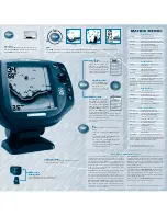
Sonar Zoom View
increases the display
resolution to separate sonar returns that are very
close together, such as those caused by fish
suspended close to the bottom or within
structure. In Zoom View, the display is split to
show a full range view on the right and the
zoomed view on the left. As the depth changes,
the zoomed view updates automatically to
display a magnified image of the bottom. The
Zoom Preview Box shows where the zoomed
view is in relation to the full range view. The
Zoom Level,
or
magnification
, is displayed in the lower left corner and can be
changed to suit conditions (see Sonar Settings - X-Press Menu). Upper and Lower
Zoom Depth Range numbers indicate the depth
of the water which is being viewed.
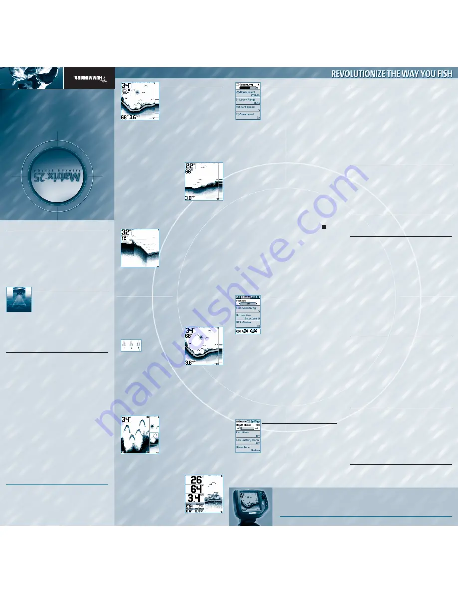
Big Digits View
provides digital data in a large,
easy-to-see format. Depth is always displayed.
Readouts for temperature, speed and Triplog
information are displayed if the appropriate
accessory is connected to the system. The Triplog
shows distance traveled, average speed, and
time elapsed since the Triplog was last reset (see
System Settings - Main Menu Setup Tab).
How Sonar Works
Sonar technology is based on sound waves. The Matrix
TM
Fishing System uses
sonar to locate and define structure, bottom contour and composition, as well
as calibrate digital depth directly below the transducer.
Your Matrix unit sends a sound wave signal and determines distance by
measuring the time between the transmission of the sound wave and when
the sound wave is reflected off of an object; it then uses the reflected signal to
interpret location, size, and composition of an object.
Sonar is very fast. A sound wave can travel from the surface to a depth of 240
ft (70 m) and back again in less than ¼ of a second. It is unlikely that your boat
can "outrun" this sonar signal.
DualBeamPLUS™ Sonar
Your Matrix 25 uses a dual frequency 200/83 kHz
DualBeamPLUS sonar system with a wide (60°) area of
coverage. DualBeamPLUS is optimized to show the
greatest bottom definition with a narrow (20°) beam, and
the fish and structure location with a wide (60°) beam.
DualBeamPLUS is ideal for a wide range of conditions - from shallow to very
deep water in both fresh and salt water. Depth capability is affected by such
factors as boat speed, wave action, bottom hardness, water conditions and
transducer installation. All sonar units typically read to deeper depths in fresh
water than in salt water. Your Matrix transducer also comes with a
temperature sensor included!
Powering Up the Unit
Turn on the Matrix unit by momentarily pressing the POWER key. A startup
screen is then displayed until the Matrix unit begins sonar operation. While
the startup screen is displayed, you may press the MENU key for the other
options listed below. If no key is pressed, the Matrix will begin Normal or
Simulator operation, depending on the presence or absence of a transducer.
The following operating states are available:
•
Normal
– Use for on the water operation with transducer connected.
•
Simulator
– Use to learn the features and functions of the Matrix unit.
Simulates on the water operation.
•
System Status
– Use to view system connections and conduct a unit
self-test.
•
PC Connect
– Use when upgrading Matrix internal software with a PC and
PC Connect cable.
The Matrix unit uses advanced transducer detection methods to determine if
a transducer is connected. If the transducer is not connected or is damaged,
the unit will select the Simulator state automatically at startup. If a
functioning transducer is connected, the unit will select the Normal operating
state automatically and the unit can be used on the water.
Note:
When operating in Simulator state with a transducer connected, Menu
setting changes are saved to memory. If a transducer is not connected, changes
will not be saved and Menu settings will revert to factory defaults every
few minutes.
Sonar Settings - X-PressTM Menu
The X-Press menu represents the settings most frequently-
used to optimize the sonar performance of the Matrix unit.
Press the MENU key once while in any of the Sonar Views,
including Big Digits, to access the following X-Press menu
settings quickly:
Sensitivity
provides advanced control over the sonar receiver.
The Matrix unit optimizes Sensitivity based on depth and
water conditions automatically; however, you also may change it manually to match
your preferences or water conditions. Increasing the sensitivity shows more sonar
returns from small bait fish and suspended debris in the water; however, the display
may become too cluttered in some water conditions. When operating in very clear
water or greater depths, increased sensitivity shows fainter returns that may be of
interest. Decreasing the sensitivity eliminates the clutter from the display that is
sometimes present in murky or muddy water. If Sensitivity is adjusted too low, the
display may not show many sonar returns that could be fish.
Beam Select -
Selects the sonar beam used in the Sonar Views. When 200 kHz is
selected, the sonar returns and Fish ID+ from the 200 kHz beam are displayed
providing greater bottom detail (typically from 2 feet to 800 feet) at any boat
speed. Using 83 kHz, the sonar returns and Fish ID+ from the 83 kHz beam are
displayed, providing greater depth capability and showing more targets in its
wider beam. The 83 kHz beam is not recommended for use when the boat is
traveling at greater than trolling speeds. When Both is selected, the unit blends
the sonar information from both beams together on the display to provide the
best sonar image and Fish ID+.
Lower Range
adjusts the lower depth range to a specific depth for the Sonar
and Big Digits Views. Automatic is the default setting. Selecting a specific
setting locks the depth range into manual mode. Advanced anglers use both
Upper and Lower Range together to view a specific depth range manually when
looking for fish or bottom structure. The Upper Range menu choice is available
when User Mode is set to Advanced (see Advanced User Mode). will be
displayed when you start manually adjusting the Lower Range to indicate that
you’re in Manual mode.
Chart Speed
determines the speed at which the bottom information moves across
the display, and consequently the amount of detail shown. A faster speed shows
more information in the Sonar View and is preferred by most anglers; however, the
bottom moves across the display quickly. The highest setting is an ultrafast mode
that provides the highest chart speed possible by slowing down other system
functions. A slower speed keeps the information on the display longer, but the
bottom and fish detail becomes compressed and may be difficult to interpret.
Regardless of the Chart Speed setting, the RTS® Window will update at the
maximum rate possible for the depth conditions. Adjust Chart Speed to your
personal preference.
Zoom Level
sets the magnification level for the Sonar Zoom View.
Sonar Settings – Main Menu Sonar Tab
Less frequently-adjusted menus are grouped into the Main
Menu System. Press the MENU key twice to access the Main
Menu System.
Fish ID+
TM
uses advanced signal processing to interpret sonar
returns and display a Fish Symbol when very selective
requirements are met. A number above the fish icon indicates
the depth of the fish. Three different fish size icons show the
intensity of the sonar return, and provide an indicator of
relative fish size. When Fish ID+ is turned off, the Matrix shows only the unprocessed
sonar returns on the display. These returns will often result in "arches" forming on
the display, indicating potential targets.
Fish Sensitivity
adjusts the thresholds of the fish detection algorithms, thus
enhancing your unit’s ability to identify sonar returns as fish icons. Selecting a
higher setting allows fainter returns to be displayed as fish icons and will increase
the number of fish icons that appear on the display. This is useful for identifying
smaller fish species or baitfish. Selecting a lower setting displays fewer fish icons
from faint sonar returns. This is helpful when seeking larger species of fish.
Bottom View
selects the method to display bottom and structure on the display.
Structure ID®
presents the graphical representation of the bottom and structure
sonar returns using only grayscale to indicate the signal strength.
WhiteLine®
highlights the strongest sonar returns from the bottom to make a distinctive
outline of the bottom contour, structure and fish.
Bottom Black
displays all
pixels below the bottom contour as black, regardless of signal strength.
RTS Window
turns the RTS window on or off in the Sonar View.
Alarm Settings - Main Menu Alarm Tab
Various audible alarms can be triggered in the Matrix unit
based on these menu settings. When an alarm is triggered,
it can be silenced by pressing the EXIT key.
Depth Alarm
sounds when the digital depth becomes
equal to or less than the menu setting.
Fish Alarm
sounds when the Fish ID+ feature displays fish
symbols that correspond to the menu setting.
Low Battery Alarm
sounds when the input battery voltage is equal to or less than
the menu setting.
Alarm Tone
selects the pitch of the alarm sound to improve audibility. As the
menu is adjusted a brief tone will be produced so that you can select the tone
that you can hear best.
System Settings - Main Menu Setup Tab
Units - Depth
selects the units of measure for all depth-related readouts.
Units - Temp
selects the units of measure for all temperature-related readouts.
This menu is only visible if temperature is available.
International Models Only.
Units - Distance
selects the units of measure for all distance-related readouts.
With Temp/Speed Accessory Only.
Units - Speed
selects the units of measure for all speed-related readouts.
With
Temp/Speed Accessory Only.
User Mode
displays additional Advanced Menus within the menu system when
set to Advanced. When set to Normal (default setting,) only the basic menu
options are shown. See Advanced User Mode section.
Triplog Reset
resets the Triplog to zero.
With Temp/Speed Accessory Only.
Language
selects the display language for menus.
International Models Only.
Restore Defaults
resets ALL menu settings to their factory defaults. Use this
menu with caution!
Advanced User Mode
Preset menu modes are available to suit your personal Angler Profile - whether
you're a Normal User or Advanced User. These Angler Profile Presets
TM
provide an
Advanced Mode for users who desire the highest level of control over the
product, and Normal Mode for users who desire the greatest simplicity and
fewest choices.
Choose User Mode from the Setup Tab and change the selection to Advanced to
access advanced features
.
A range of additional options will be displayed in the
menu system. Any changes made under the Advanced mode will remain in effect
if the unit is returned to Normal mode.
Sonar X-Press Menu - Advanced User Mode
Upper Range
Adjusts the Upper Depth Range to a specific depth for the Sonar and Big
Digits Views. (0 to 1190 feet, Default: 0)
83 kHz Sensitivity
Adjusts the sensitivity applied to the 83kHz beam to be higher or lower
than the overall sensitivity settting. (-10 to +10, Default=0)
Sonar Menu - Advanced User Mode
Surface Clutter
Adjusts the filter that removes surface clutter noise caused by algae and
aeration. The lower the setting, the less surface clutter will be displayed.
(Low=1, High=10, Default=Low)
Noise Filter
Adjusts the sonar Noise Filter to limit interference from sources such as
your boat engine, turbulence, or other sonar devices for best display
performance. (Off, Low, Medium, High, Default=Low)
Note: The Off setting removes all filtering; Low, Medium and High settings add
progressive filtering of the sonar returns. In some deep water situations, the
High setting may actually hinder your unit’s ability to find the bottom.
Water Type
Configures unit for type of water conditions. (Salt, Fresh, Default=Fresh)
Note: In salt water, what would be considered a large fish might be 2 to 10
times bigger than a large fish in fresh water (depending on the type of fish you
are seeking). The salt water setting allows for a greater range in fish size
adjustment to account for this. Also, make sure that the Water Type is set
accurately, especially in salt water, as this can affect the accuracy of deep water
depth readings.
Max Depth
Adjusts the maximum depth of unit operation.
(Auto, 10 to 1200 feet, Default=Auto)
Note: The performance of your unit can be tuned to the maximum depth you
will be fishing in by setting this menu choice. When a maximum depth is set,
the unit will not attempt to acquire sonar data below that depth, thus
increasing overall performance. When the Max Depth is set to Auto, the unit
will acquire bottom readings as needed (within the capacity of the unit).
System Setup Menu - Advanced User Mode
S
elect Views
Access submenus to hide or show individual views available on
the Matrix unit. This includes new views added when new accessories
are connected.
Select Readouts
Accesses submenus to hide or show individual digital readouts on the
Sonar View. This includes readouts from supported accessories.
Depth Offset
Adjusts digital depth readout to indicate depth from waterline or keel.
Enter a positive vertical measurement (+1, +2, +3 feet) from the
transducer to waterline to read the depth from the waterline. Enter a
negative vertical measurement (-1, -2, -3 feet) from the transducer to keel
to read the depth from the keel. (-10 feet to +10 feet, Default=0)
Temperature Offset
Adjusts temperature readout by entered amount to match other gauges.
(-10 to +10, Default=0)
Speed Calibration
Adjusts speed readout by entered percentage to match other gauges.
(-20% to +20%, Default=0)
NMEA Output
Enables or disables NMEA 0183 depth sentence. (On, Off, Default=Off)
Using System Status
When System Status is selected on the Start-Up menu, the Matrix displays a
series of three views to provide information about the unit.
Self Test
displays results from internal diagnostic self test, including unit serial
number, software revision, total hours of operation and the input voltage from
the power source.
Accessory Test
lists the accessories connected to the system. Note that the speed
accessory is only detected when the paddlewheel is moving.
Sonar Test
displays unprocessed sonar returns on the display to confirm sonar is
operational.
Exit System Status mode by powering the unit off.
Using PC Connect
When PC Connect is selected from the Startup Menu, the Matrix unit enters a
communication mode and waits for a connection with a PC. Complete
instructions are included with the PC Connect accessory (AS-PC). Exit PC Connect
mode by powering the unit off.
Thank you for c
hoosing Humminbird®, America's#1 name in fishfinders. Humminbird has built its reputation by
designing and manufacturing t
op-quality
, thoroughly reliable marine equipment. Y
our Humminbird is designed for
trouble-free use in ev
en the harshest marine envir
onment. In the unlik
ely event that your Humminbird does require
repairs, we of
fer an e
xclusiv
e Service P
olicy - free of c
harge during the first y
ear after purc
hase, and available at a
reasonable rat
e af
ter the one-
year period. For c
omplete
details, see the separ
ate warr
anty card included with your unit.
We enc
ourage you t
o read this oper
ation manual carefully in order t
o get full benefit fr
om all the features and
applications of your Humminbird produc
t.
Contac
t our Customer R
esource Cent
er at either 1-334-
687-0503 or w
ww
.humminbird.com.
WARN
ING! This device should not be used as a na
vigational aid t
o prev
ent collision, gr
ounding, boat damage, or personal injur
y. When the
boat is moving
, wat
er depth may change t
oo quickly t
o allow time
for you t
o reac
t. Always operat
e the boat at v
ery
slow speeds if you
suspect shallow wat
er or submerged objec
ts.
Matrix
TM
, Humminbird®, WeatherSense
TM
, Selectiv
e Fish ID+
TM
, WhiteLine®, R
TS®, X-Press
TM
Menu, Selectiv
e Fish ID+
TM
, Fish ID+
TM
,
Structure I
D®, TrueArc
h
TM
, UltraBlac
k
TM
, Angler Profile Presets
TM
are trademark
ed by or registered tr
ademarks of Tec
hsonic Industries, Inc.
© 2003.
All rights reserved.
Thank you for c
hoosing Humminbird®, America's#1 name in fishfinders. Humminbird has built its reputation by
designing and manufacturing t
op-quality
, thoroughly reliable marine equipment. Y
our Humminbird is designed for
trouble-free use in ev
en the harshest marine envir
onment. In the unlik
ely event that your Humminbird does require
repairs, we of
fer an e
xclusiv
e Service P
olicy - free of c
harge during the first y
ear after purc
hase, and available at a
reasonable rat
e af
ter the one-
year period. For c
omplete details
, see the separat
e warranty card included with your unit.
We enc
ourage you t
o read this oper
ation manual carefully in order t
o get full benefit fr
om all the features and
applications of your Humminbird produc
t.
Contac
t our Customer R
esource Cent
er at either 1-334-
687-0
503 or ww
w.humminbird.c
om.
WARN
ING! This device should not be used as a na
vigational aid t
o prev
ent collision, gr
ounding, boat damage, or personal injur
y. When the
boat is moving
, wat
er depth may change t
oo quickly t
o allow time
for you t
o reac
t. Always operat
e the boat at ver
y slow speeds
if you
suspect shallow wat
er or submer
ged objects.
Matrix
TM
, Humminbird®, WeatherSense
TM
, Selectiv
e Fish ID+
TM
, WhiteLine®, R
TS®, X-Press
TM
Menu, Selectiv
e Fish ID+
TM
, Fish ID+
TM
,
Structure I
D®, TrueArc
h
TM
, UltraBlac
k
TM
, Angler Profile Presets
TM
are trademark
ed by or registered tr
ademarks of Tec
hsonic Industries, Inc.
© 2003.
All rights reserved.
Product specifications and features are subject to change without notice.
Temp/Speed Accessory is optional.
kHz
Sonar Zoom View shown
with Structure ID® on
Big Digits View shown with
Bottom View set to WhiteLine
Barometer and Temp/Speed
accessories are optional.
Additional purchase required.
Temp/Speed Accessory is optional.
WARNING:
Disassembly and repair of this electronic unit should only be
performed by authorized service personnel. Any modification of the serial
number or attempt to repair the original equipment or accessories by
unauthorized individuals will void the warranty. Handling and/or opening this
unit may result in exposure to lead, in the form of solder.
WARNING:
This product contains lead, a chemical known to the state of
California to cause cancer, birth defects and other reproductive harm.
M


