1
532594-2_A
SOLIX® SERIES IN-DASH MOUNTING Installation Guide
Overview
Following are instructions for the in-dash mount installation of the SOLIX control head. We
encourage you to read this guide before starting the installation, so you may understand the
installation requirements.
Technical Support:
If you find that any items are missing from your installation kit, visit our Web site
at
humminbird.com
or call Humminbird® Technical Support at
1-800-633-1468
.
Supplies:
In addition to the hardware supplied with your accessory, you will need a drill and
various drill bits, a cutting tool for the dashboard material, various hand tools (including a 3/8"
(9.5 mm) adjustable wrench and 3/8" socket wrench or nut driver), safety glasses and dust mask,
masking tape, and a towel or cloth.
WARNING!
Do NOT use power tools to secure the hardware. We encourage you to read the
installation instructions so you may understand the installation requirements.
NOTE:
Product supplies and features are subject to change without notice.
1
|
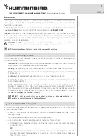
Plan the Mounting Location
Start by locating a suitable, flat area of the dashboard for mounting. Consider the following to find
the best mounting location:
Δ Interference:
The mounting location must provide adequate distance from electric motors or
any equipment that may cause electronic interference.
Δ Stability:
The mounting area should be protected from waves, shock, vibration, and water.
Δ Depth:
The mounting area should have a depth of 4" (102 mm) to allow space for the control
head and cables.
Δ Ventilation:
The area beneath the mounting surface should be well-ventilated.
Δ Accessibility:
The location should be easily accessible for all cables to reach the ports on the
back of the control head.
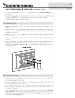
Δ Multiple Control Heads:
If you plan to install more than one control head side by side, leave
a minimum space of 1 7/16" (36.2 mm) between mounting holes. This will allow for 1/4" (7
mm) between control heads with the covers installed and space for the bracket under the
dashboard. Take your measurement from the front, left or right side of the control head cut
line.
See the template for more information.
NOTE:
If a cable is too short for your application, extension cables are available. For
assistance, contact Humminbird Technical Support.
2
|
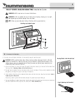
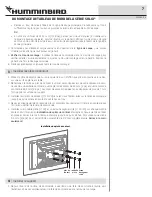
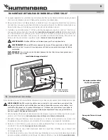
Cut the In-Dash Mounting Hole
To in-dash mount the SOLIX control head, start by placing the components on the surfaces where
you intend to install them.
1. Review the instructions, measurements, and cutting options indicated on the In-dash
Mounting Template.
2. Tape the template to the chosen in-dash mounting location.
3. Using the template, select the cutting method that is best for your boat:
Δ
Drill one entry hole away from the main cut line that is large enough to insert the blade of
your cutting tool.
OR
Δ
Using a 7/16" drill bit, drill the 4 corner holes (inside the main cut line) as shown on the
template. Use one of the corner holes as an entry hole, or drill an additional entry hole away
from the main cut line.