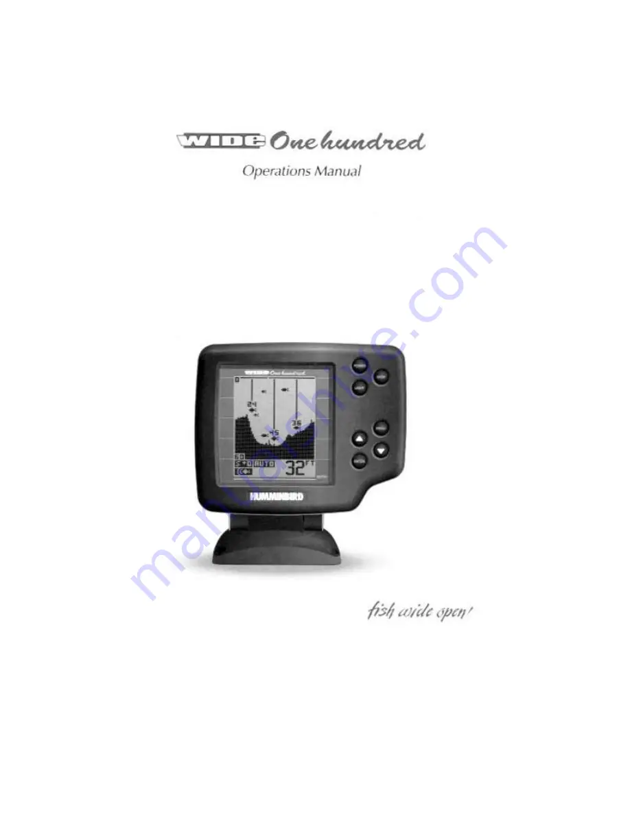
background image


Summary of Contents for Wide 100

Page 1: ......

Page 2: ...our number listed in the Customer Support section INSTALLATION OVERVIEW Your Humminbird fishfinder consists of two primary components to install the control head and the transducer The control head c...

Page 3: ...should the boat strike debris in the water or when trailering As an alternative to transom mounting it is possible on many fiberglass hulled boats to glue the transducer on the inside of the boat hull...

Page 4: ...other surface Trolling Motor Mounting The standard transducer can also be adapted to mount on most trolling motors using a different accessory kit This accessory includes a bracket and hose clamp that...

Page 5: ...minbird fishfinder The installation guide included on the next few pages provides detailed step by step instructions for installation of the control head and transducer For transom mount transducer in...

Page 6: ...the propeller s This turbulent water is normally confined to areas immediately aft of ribs strakes or rows of rivets on the bottom of the boat and in the immediate area of the propeller s Figure 1 On...

Page 7: ...g a 5 32 4mm bit drill the two holes to a depth of approximately 1 3cm On fiberglass hulls it is best to start with a smaller bit and use progressively larger drill bits to reduce the chance of chippi...

Page 8: ......

Page 9: ...urther adjustment may be necessary to refine the instillation after high speed testing 1 First adjust the pivot angle of the transducer body so its length is parallel with the length of hull of the bo...

Page 10: ...mounting bracket Drill this hole and install the screw after final testing and adjustments have been completed...

Page 11: ...erference If the cable is too short extension cables are available to extend the transducer cable up to a total of 50 15 m Call Humminbird Customer Support for more information Follow these steps to r...

Page 12: ...unting Location Begin the transducer installation by determining where inside the hull to install the transducer Consider the following to find the best location Observe the outside of the boat hull t...

Page 13: ...The transducer cannot transmit through air The water purges any air from between the transducer and the hull and fills any voids in the coarse fiberglass surface...

Page 14: ...dry the mounting surface If the surface is excessively rough it may be necessary to sand the area to provide a smooth mounting surface Ensure the mounting area is clear and dry 3 Mix an ample quantit...

Page 15: ...supplied hole cover The mounting surface should be adequately supported to protect the fishfinder from excessive wave shock and vibration and provide visibility while in operation The mounting area sh...

Page 16: ...fuse in the connection If you must wire the control head directly to a battery be sure to install an inline fuse holder...

Page 17: ...mounting surface mark and drill a 1 25mm hole centered between the four mounting holes Figure 22 Note if the cables must pass through the mounting surface at a different location drill the 1 25mm hol...

Page 18: ...Optional If the cables pass outside the mounting bracket install the hole cover over the hole and fasten in place using the two 8 x 7 8 22mm wood screws Figure 24...

Page 19: ...ll the excess cable from beneath the mounting surface so the connector holder aligns with the mounting holes on the front of the mounting bracket Figure 27 3 Snap the support plate to the rear of the...

Page 20: ...rmal operation unless you choose another option If you do not press any button before the timer reaches 0 the normal operation screen is displayed If the boat is in water sonar data appears If the bot...

Page 21: ...rmation or the view directly under your boat If your boat is moving an accurate depiction of the terrain you have just covered is created on screen If the bottom is visible on screen with a digital de...

Page 22: ...peration the Wide One Hundred unit responds to control inputs as if it is in actual operation so feel free to experiment with the many features and functions to customize the Wide One Hundred unit for...

Page 23: ...n screen STOP will retain the menu on screen until STOP is pressed again The transmitted sonar signal travels downward and is reflected back toward the surface by the bottom or other objects for displ...

Page 24: ...he sonar returns Remember once a setting has been changed the Wide One Hundred will remember that setting until it is changed again or until the unit is powered off Sensitivity As the Wide One Hundred...

Page 25: ...justment manually By pressing ENTER you can select manual operation meaning the unit will no longer adjust the depth range automatically The depth range selected is controlled by the UP and DOWN arrow...

Page 26: ...To enable zoom adjust the depth of the zoom range first using the UP and DOWN Arrow buttons until the upper and lower limit numbers correspond with the range you wish to view then enable Zoom using t...

Page 27: ...water beneath your boat The Fish Alarm has 3 different settings which correspond to the 3 different size fish targets shown on screen To enable Fish Alarm use the UP and DOWN arrow buttons to adjust...

Page 28: ...interpretation of targets and displays the raw sonar information as it is received Advanced users may prefer this type of presentation so they can make there own interpretation from the information d...

Reviews:

Related manuals for Wide 100