


Summary of Contents for Wide 2000
Page 1: ......
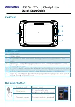
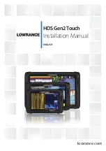
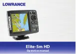
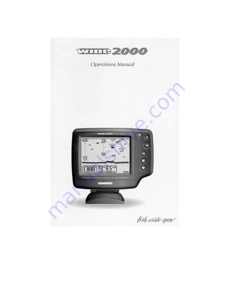
The Humminbird Wide 2000 is a high-performance fishfinder with a user-friendly interface. For detailed instructions on how to operate this device, download the free Operation Manual from 88.208.23.73:8080. This manual will guide you through the setup and use of the Wide 2000, ensuring optimal performance on your next fishing trip.
Page 1: ......