
Summary of Contents for Wide Optic
Page 1: ......
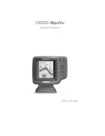
The Humminbird Wide Optic fish finder is a top-of-the-line tool for anglers looking to enhance their fishing experience. With advanced features such as dual beam sonar and GPS compatibility, this device will help you locate fish with ease. For more information, download the free Operation Manual from 88.208.23.73:8080.
Page 1: ......