

Summary of Contents for Wide Paramount
Page 1: ......
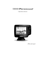
The Humminbird Wide Paramount is a high-quality fish finder with advanced features for avid anglers. Make sure to download the Operation Manual for detailed instructions on how to maximize its performance. Get your free manual at 88.208.23.73:8080 and start exploring the waters with confidence.
Page 1: ......