

Summary of Contents for Wide Vision
Page 1: ......
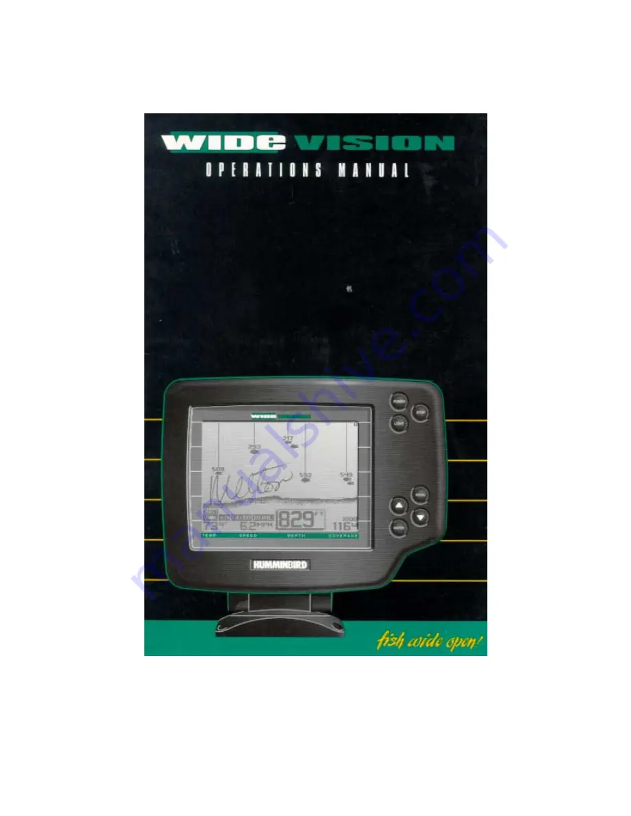
The Humminbird Wide Vision is a cutting-edge fishfinder with a wide-screen display for optimal underwater visibility. To maximize your fishing experience, be sure to download the free Operation Manual from 88.208.23.73:8080 for detailed instructions on how to use this exceptional device. Enjoy seamless navigation and accurate fish tracking with ease.
Page 1: ......