background image

1330SB-XLSb

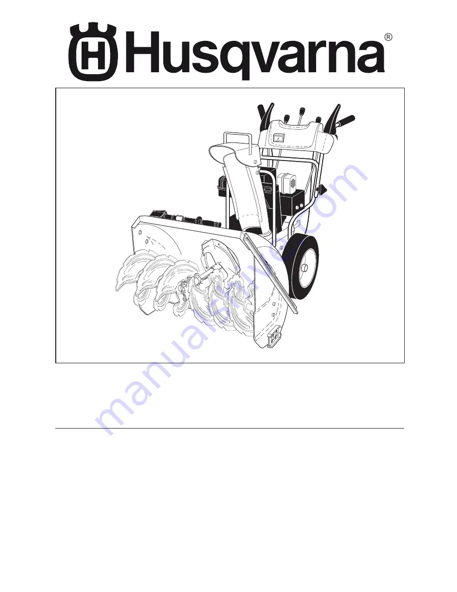
Owner's Manual

 / 96193004100 / 2008-11

Summary of Contents for 1330SB-XLSB

Page 1: ...1330SB XLSb Owner s Manual 96193004100 2008 11 ...

Page 2: ... the machine Operation 1 Do not put hands or feet near or under rotating parts Keep clear of the discharge opening at all times 2 Exercise extreme caution when operating on or cross ing gravel drives walks or roads Stay alert for hidden hazards or traffic 3 After striking a foreign object stop the engine motor remove the wire from the spark plug disconnect the cord on electric motors thoroughly in...

Page 3: ...10 Never direct the discharge toward people or areas where property damage can occur Keep children and others away 11 Do not overload the machine capacity by attempting to clear snow at too fast a rate 12 Never operate the machine at high transport speeds on slippery surfaces Look behind and use care when operating in reverse 13 Disengage power to the collector impeller when snow thrower is transp...

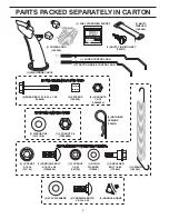
Page 4: ... 1 4 20 191730 1 NYLON WASHER 179246 1 SHOULDER BOLT 1 4 20 179829 1 SPRING 184505 1 LOCKNUT 3 8 73800600 3 RETAINER SPRINGS 169675 6 LOCKNUTS 1 4 20 73800400 1 TRACTION DRIVE CONTROL ROD EXTRA SHEAR BOLTS AND NUTS ROTATOR HEAD MOUNTING CHUTE DEFLECTOR REMOTE CONTROL 1 AUGER CONTROL ROD 1 SAFTEY IGNITION KEY 193071 1 FUEL STABILIZER PACKET 1 MULTI WRENCH 180684 2 FLAT WASHERS 2 CARRIAGE BOLTS 3 8 ...

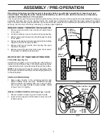
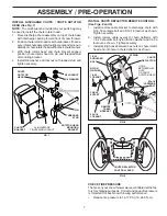
Page 5: ...ls except plastic tie holding speed control rod to lower handle 5 Remove the two 2 plastic ties securing the upper handle to the pallet 6 Remove snow thrower from carton and check carton thoroughly for additional loose parts HOW TO SET UP YOUR SNOW THROWER TOOL BOX See Fig 10 A toolbox is provided on your snow thrower The toolbox is located on top of the belt cover Store the extra shear bolts nuts...

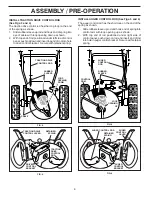
Page 6: ...er spring AUGER CONTROL LEVER AUGER CONTROL ROD AUGER CONTROL BRACKET RETAINER SPRING FIG 6 INSTALL TRACTION DRIVE CONTROL ROD See Figs 3 and 4 The traction drive control rod has the long loop on the end of the spring as shown 1 Slide rubber sleeve up rod and hook end of spring into eye of cable with loop opening down as shown 2 With top end of rod positioned under left side of control panel push ...

Page 7: ...ute with 5 16 18 carriage bolt and 5 16 18 locknut as shown Tighten securely 2 Install remote cable eyelet to chute deflector with 1 4 20 shoulder bolt nylon friction washer and 1 4 20 locknut as shown Tighten securely 3 Install spring hooks between hex nuts on chute rotator head and into hole in chute deflector as shown CHUTE DEFLECTOR CONTROL LEVER FIG 9 CHECK TIRE PRESSURE The tires on your sno...

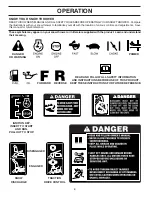
Page 8: ...s Save this manual for future reference These symbols may appear on your snow thrower or in literature supplied with the product Learn and understand their meaning FORWARD PRIMER IGNITION KEY INSERT TO START AND RUN PULL OUT TO STOP READ AND FOLLOW ALL SAFETY INFORMATION AND INSTRUCTIONS BEFORE USE OF THIS PRODUCT KEEP THESE INSTRUCTIONS FOR FUTURE REFERENCE DANGER OR WARNING REVERSE SNOW DISCHARG...

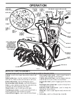
Page 9: ...when snow thrower is not in use Electric start button used for starting the engine Recoil auxiliary starterhandle usedforstartingengine Primer pumps additional fuel from the carburetor to the cylinder for use when starting a cold engine Choke Control used for starting a cold engine Throttle engine control used to select either FAST or SLOW engine speed and to STOP the engine LH and RH turn trigger...

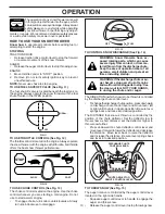
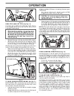
Page 10: ...ure lever springs back and locks into desired position The operation of any snow thrower can result in foreign objects thrown into the eyes which canresultinsevereeyedamage Alwayswear safety glasses or eye shields while operating your snow thrower or performing any adjust ments or repairs We recommend standard safety glasses or a wide vision safety mask worn over spectacles HOW TO USE YOUR SNOW TH...

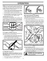
Page 11: ...9 NOTE The wrench provided in your parts bag may be used to adjust the skid plates Skid plates are located on each side of the auger housing and adjust the clearance between the scraper bar and the ground surface Adjust skid plates evenly to proper height for current surface conditions For removal of snow in normal conditions such as a paved driveway or sidewalk place skid plates in the highest po...

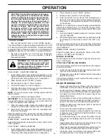
Page 12: ...nance section of this manual TO USE DRIFT CUTTERS See Fig 20 Use the drift cutters to cut through deep snowdrifts that are higher than the front of the snow thrower Loosen adjustment nuts enough to allow drift cutter to be raised to highest position and tighten nuts securely Repeat for opposite side of snow thrower When not using drift cutters loosen adjustment nuts lower to storage position and t...

Page 13: ...parately in parts bag intoignitionslotuntilitclicks DONOTturnthekey Keep the extra safety ignition key in a safe place 2 Place throttle control in FAST position 3 Rotate choke control to FULL position 4 Push the primer four 4 times if the temperature is below 15 F or two 2 times if temperature is between 15 and 50 F If temperature is above 50 F priming is not necessary NOTE Over priming may cause ...

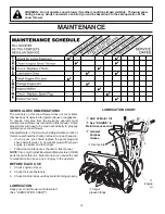
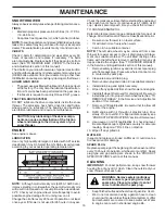
Page 14: ...ll help your engine run better and last longer Follow the maintenance schedule in this manual NOTE Use only Original Equipment Manufacturer OEM parts to service this unit Failure to do so can cause the unit to malfunction and pose a risk of injury to the operator BEFORE EACH USE 1 Check engine oil level 2 Check for loose fasteners 3 Checkcontrolstobesuretheyarefunctioningproperly LUBRICATION Keep ...

Page 15: ...ment of a suitable container The unit tilted resting on the frame with the left wheel removed will help drain any oil trapped inside the engine See TO REMOVE WHEELS in the Service and Adjustments section of this manual 1 Remove safety ignition key and disconnect spark plug wire from spark plug Place wire where it cannot come in contact with spark plug 2 Clean area around drain plug 3 Remove drain ...

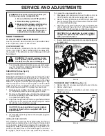
Page 16: ...e in contact with spark plug 3 Alignholeinaugerhubwithholeinaugershaftandinstall anew1 4 20x2 shoulder shearboltandspacer Install 1 4 20 lock nut and tighten securely CAUTION Do not substitute Use only original equipment shear bolts as supplied with your snow thrower 4 Insert safety ignition key and reconnect spark plug wire to spark plug IMPELLER SHEAR BOLTS The impeller is secured to the impelle...

Page 17: ...ile separating the auger housing from the frame assembly it is important that an assistant stand in the operating position and hold the snow thrower handles Seriouspersonalinjuryand or damage to the unit could occur if the snowthrowershouldfallduringthebelt changing process HINT Insert a 3 8 drive ratchet in the ON position into the square hole in idler arm and rotate ratchet clockwise to relieve ...

Page 18: ...or Do not drain the gas tank and carburetor if using fuel stabilizer ENGINE OIL Drain oil with engine warm and replace with clean engine oil See ENGINE in the Maintenance section of this manual CYLINDER 1 Remove spark plug 2 Pour one ounce 29 ml of oil through spark plug hole into cylinder 3 Pull recoil starter handle slowly a few times to distribute oil 4 Replace with new spark plug OTHER Remove ...

Page 19: ...sition 1 Move choke to OFF position runs roughly 2 Blockage in fuel line 2 Clean fuel line 3 Stale fuel 3 Drain tank and refill with fresh clean fuel 4 Water in fuel 4 Drain fuel tank and carburetor refill tank with fresh gasoline 5 Carburetor is in need of 5 Contact a qualified service center adjustment or overhaul Excessive 1 Loose parts or damaged 1 Tighten all fasteners Replace damaged parts v...

Page 20: ...G IMPELLER ASSEMBLY SNOWTHROWER MODELNO 1330SB XLSB 96193004100 PRODUCTNO 9619300 41 2 EXPLODED 2 10 9 1 11 11 3 12 12 4 13 14 15 17 8 7 11 5 6 11 16 18 35 19 21 22 23 24 25 23 22 21 20 36 26 27 28 30 29 31 31 32 33 34 01 07 004 B ...

Page 21: ...0 04 00 NUT 1 4 20 10 874 78 04 26 SCREW 1 4 20 X 625 11 532 15 53 77 NUT 5 16 18 12 532 16 31 83 SCREW 5 16 18 X 625 13 819 11 15 07 WASHER 14 810 04 05 00 LOCKWASHER 5 16 15 874 94 05 16 SCREW 5 16 18 X 1 00 16 532 18 03 55 CARRIAGE BOLT 17 532 19 41 89 SCREW 13 16 X 625 18 532 40 77 60 PLUG 19 532 40 77 61 GEARBOX COVER RH 20 532 40 77 66 GASKET 21 532 40 77 70 SEAL 22 532 40 77 62 BEARING 23 5...

Page 22: ... LH 2 532 42 17 27 AUGER ASSEMBLY 30 RH 1 2 3 5x 4 5x 01 07 023 B 1 532 42 17 13 AUGER HOUSING 2 532 40 76 45 SCRAPPER BAR 3 872 27 05 05 CARRIAGE BOLT 5 16 18 X 625 4 532 15 53 77 NUT 5 16 18 NOTE All component dimensions given in U S inches 1 inch 25 4 mm IMPORTANT Use only Original Equipment Manufacturer O E M replacement parts Failure to do so could be hazardous damage your snow thrower and vo...

Page 23: ...AINER 2 532 41 18 33 AUGER BALL BEARING 3 532 17 95 82 SCREW 5 16 18 X 1 00 1 1 2 3 3 2 01 11 002 A 1 532 40 78 34 SKID PLATE 2 872 27 05 06 CARRIAGE BOLT 5 16 18 X 750 3 532 75 11 53 NUT 5 16 18 NOTE All component dimensions given in U S inches 1 inch 25 4 mm IMPORTANT Use only Original Equipment Manufacturer O E M replacement parts Failure to do so could be hazardous damage your snow thrower and...

Page 24: ... 16 18X 750 3 532 17 92 46 PLASTIC WASHER 4 810 04 05 00 LOCKWASHER 5 16 5 532 12 86 38 NUT 5 16 18 01 17 003 B 1 2 3 3 2 4 4 NOTE All component dimensions given in U S inches 1 inch 25 4 mm IMPORTANT Use only Original Equipment Manufacturer O E M replacement parts Failure to do so could be hazardous damage your snow thrower and void your warranty 1 532 18 25 16 WEIGHT BAR 2 872 11 05 10 CARRIAGE ...

Page 25: ...AINER STRAP 10 532 17 98 29 SHOULDER BOLT 1 4 20 X 375 11 532 17 92 46 PLASTIC WASHER 12 532 19 17 30 NUT 1 4 20 13 872 25 05 05 CARRIAGE BOLT 3 8 16 X 625 14 532 75 11 53 NUT 5 16 18 15 532 18 45 05 DEFLECTOR SPRING 16 532 42 06 79 SERVICE PART DEFLECTOR CONTROL 17 532 42 11 64 SERVICE PART DEFLECTOR CABLE GRAY 18 532 42 11 38 DEFLECTOR SHIELD 19 532 42 32 47 DEFLECTOR SHIELD STRAP NOTES 1 ITEMS ...

Page 26: ...age your snow thrower and void your warranty 1 2 01 15 008 A KEY PART NO NO DESCRIPTION KEY PART NO NO DESCRIPTION 1 532 42 12 31 STEER CABLE 2 874 04 10 24 SCREW 10 24 X 1 50 1 2 2 3 6 6 4 5 01 09 008 B 1 532 42 11 60 LEVER CABLE ROTATOR ASSEMBLY GRAY 2 817 50 10 10 SCREW 10 24 X 625 3 532 42 06 78 ROTATOR HEAD 4 532 42 11 61 ROTATOR PIVOT BRACKET 5 532 42 06 75 PULLEY PIVOT 6 532 42 11 62 CABLE ...

Page 27: ...00 41 1 4 5 6 7 7 8 10 11 14 14 12 13 13 12 2 3 9 9 8 01 08 012 A KEY PART NO NO DESCRIPTION 1 532 41 55 39 CONTROL PANEL 2 532 42 17 06 CONTROL LEVER LH 3 532 42 17 07 CONTROL LEVER RH 4 532 41 55 46 TRACTION ROD ARM 5 532 42 14 92 IMPELLER ROD ARM 6 532 41 26 77 INTERLOCK ROD 7 532 41 26 80 SPACER 8 532 16 96 75 RETAINER 9 817 06 04 08 SCREW 1 4 20 X 50 10 532 41 42 80 KNOB BLACK 11 532 41 42 81...

Page 28: ...5 5 10 10 01 08 011 A KEY PART NO NO DESCRIPTION KEY PART NO NO DESCRIPTION 1 532 42 17 08 PLOW HANDLE LH 2 532 42 17 09 PLOW HANDLE RH 3 532 19 69 44 PANEL BRACKET LH 4 532 19 69 43 PANEL BRACKET RH 5 532 41 45 15 HEATED HANDLE GRIP 6 874 78 05 12 SCREW 5 16 18 X 750 7 874 78 05 24 SCREW 5 16 18 X 1 50 8 532 75 11 53 NUT 5 16 18 9 532 15 54 15 WASHER 10 532 17 87 75 POP RIVET 1 8 2 4 4 4 3 3 1 4 ...

Page 29: ...s damage your snow thrower and void your warranty KEY PART NO NO DESCRIPTION 2 5 7 8 9 11 11 10 1 3 6 01 12 002 C 1 532 42 17 63 IMPELLER ROD ASSEMBLY 2 532 18 04 85 TRACTION ROD ASSEMBLY 3 532 18 77 82 SHIFTER ROD TOP 4 532 18 77 84 SHIFTER ROD BOTTOM 5 532 18 04 47 SPRING SLEEVE 6 532 19 20 91 SPRING SLEEVE 7 532 17 86 69 IMPELLER SPRING 8 532 18 09 26 TRACTION SPRING 9 872 27 05 06 CARRIAGEBOLT...

Page 30: ...01 08 007 B 1 532 41 62 88 INTERLOCK SPRING 2 532 41 45 72 INTERLOCK CAM 3 532 17 88 31 TORSION SPRING 4 532 16 96 75 RETAINER 5 817 06 04 10 SCREW 1 4 20 X 625 6 532 42 18 14 INTERLOCK STOP KEY PART NO NO DESCRIPTION KEY PART NO NO DESCRIPTION 1 4 4 5 5 2 3 8 6 7 01 10 010 A 1 532 42 13 51 CONSOLE PANEL GRAY 2 532 42 14 48 HEADLIGHT BEZEL GRAY 3 532 17 86 66 HALOGEN HEADLIGHT 4 532 18 44 71 SHOUL...

Page 31: ...ement parts Failure to do so could be hazardous damage your snow thrower and void your warranty KEY PART NO NO DESCRIPTION 3 4 6 2 1 4 3 7 7 5 6 2 8 9 01 03 003 A 1 532 40 43 08 AXLE SHAFT 2 532 18 77 94 SPACER 3 532 17 46 97 THRUST WASHER 4 532 17 98 30 BEARING 5 532 14 63 15 SCREW 5 16 18 X 625 6 817 49 05 08 BOLT 5 16 18 X 500 7 532 15 54 43 CLIK PIN 8 874 78 06 32 SCREW 3 8 16 X 2 00 9 873 80 ...

Page 32: ...O 1330SB XLSB 96193004100 PRODUCTNO 9619300 41 01 02 002 F 2 1 8 7 6 5 4 3 1 2 34 33 32 31 30 29 28 27 25 24 29 28 27 36 23 20 13 12 11 10 15 22 21 19 18 17 16 44 40 20 9 20 26 26 14 48 48 20 47 20 47 45 46 42 43 41 27 38 39 37 35 49 50 51 4 ...

Page 33: ...R CABLE BRACKET 18 532 18 77 87 CONTROL ARM 19 532 19 19 93 FRONT CABLE BRACKET 20 532 15 00 78 SCREW 5 16 18 X 750 21 532 08 79 30 CLIP 22 817 39 12 08 SCREW 12 X 50 23 532 17 53 31 BUSHING 24 532 19 36 07 BELT GUIDE 25 811 05 05 00 LOCKWASHER 5 16 26 817 49 04 08 SCREW 1 4 20 X 500 27 532 05 92 89 WASHER 28 810 04 05 00 LOCKWASHER 5 16 29 874 61 05 16 SCREW 5 16 18 X 1 00 30 532 40 94 75 SPACER ...

Page 34: ...eplacement parts Failure to do so could be hazardous damage your snow thrower and void your warranty KEY PART NO NO DESCRIPTION REPAIR PARTS DRIVE SNOWTHROWER MODELNO 1330SB XLSB 96193004100 PRODUCTNO 9619300 41 1 01 01 001 B 2 3 1 532 41 47 71 TORQUE STRAP 2 532 40 78 58 ANTI ROTATE BRACKET 3 532 15 00 78 SCREW 5 16 18 X 750 ...

Page 35: ...rdous damage your snow thrower and void your warranty KEY PART NO NO DESCRIPTION KEY PART NO NO DESCRIPTION 1 2 3 4 4 5 5 6 6 01 00 021 B B S ENGINE MODEL 21M414 1182 E1 1 532 41 53 40 FRAME 2 532 40 37 32 BOTTOM PAN 3 532 40 38 70 ENGINE MOUNT PLATE 4 532 15 04 06 BOLT 3 8 16 5 532 15 00 78 SCREW 5 16 18 X 750 6 532 18 44 71 SCREW 10 24 X 625 01 04 002 B 3 4 1 2 1 532 40 91 61 COVER ASSEMBLY 2 53...

Page 36: ... 70 WHEEL ASSEMBLY LH 2 532 42 20 69 WHEEL ASSEMBLY RH 1 2 01 15 002 A 1 532 41 52 63 STEER CABLE BRACKET LH 2 532 18 78 59 STEER CABLE BRACKET RH NOTE All component dimensions given in U S inches 1 inch 25 4 mm IMPORTANT Use only Original Equipment Manufacturer O E M replacement parts Failure to do so could be hazardous damage your snow thrower and void your warranty ...

Page 37: ...92 82 SQUARE KEY 10 532 19 49 40 AXLE LOBE 11 532 17 46 97 THRUST WASHER 12 532 19 95 19 STEERING YOKE 13 532 18 41 97 STEERING BRACKET 14 817 49 05 08 SCREW 5 16 18 X 50 15 532 19 95 11 PIVOT BRACKET 16 532 19 95 18 BELLCRANK 17 532 18 18 47 BELLCRANK PIN 18 817 60 04 06 SCREW 1 4 20 X 375 19 532 40 50 77 STEERING LINK 20 532 70 02 79 RETAINER 21 532 08 51 79 RETAINER 22 532 19 38 85 SPRING 23 53...

Page 38: ...PART NO NO DESCRIPTION 1 532 19 85 63 POWER CORD 2 532 16 96 75 RETAINER PIN 3 532 18 06 84 WRENCH 4 532 18 45 05 REMOTE SPRING 5 532 17 98 29 SHOULDER BOLT 1 4 20 6 532 17 92 46 NYLON WASHER 1 4 20 7 532 19 17 30 LOCKNUT 1 4 20 8 872 25 05 05 CARRIAGE BOLT 5 16 18 X 5 8 9 532 75 11 53 LOCKNUT 5 16 18 10 873 80 06 00 LOCKNUT 3 8 16 11 819 13 13 16 WASHER 3 8 12 532 19 86 36 SHEAR BOLT 1 4 20 X 1 3...

Page 39: ... thrower and void your warranty KEY PART NO NO DESCRIPTION 1 532 18 10 37 DECAL DANGER 2 532 42 37 17 DECAL HUSQVARNA 1330SB XLSB 3 532 18 10 35 DECAL DANGER DEFLECTOR 4 532 18 10 42 DECAL DANGER 5 532 42 37 16 DECAL HUSQVARNA 1330SB XLSB 6 532 18 10 33 DECAL INSTRUCTION 7 532 18 37 30 DECAL REMOTE DEFLECTOR 9 532 41 54 75 DECAL SPEED CONTROL 11 532 41 53 99 DECAL LH TRIGGER 12 532 41 53 98 DECAL ...

Page 40: ...t time of purchase SECTION 2 HUSQVARNA S OBLIGATIONS UNDER THE WARRANTY Husqvarna will repair or replace defective components without charge for parts or labor if a component fails because of a defect in material or workmanship during the warranty period SECTION 3 ITEMS NOT COVERED BY THIS WARRANTY The following items are not covered by this warranty 1 Normal customer maintenance items which becom...

Reviews: