background image

BY  CUSTOM  EQUIPMENT  LLC

OPERATIONS & SAFETY MANUAL

SELF-PROPELLED AERIAL WORK PLATFORM

SUPO-713
REV A

HB-1030CE

HB-1430CE

SERIES III

Summary of Contents for HB-1030CE

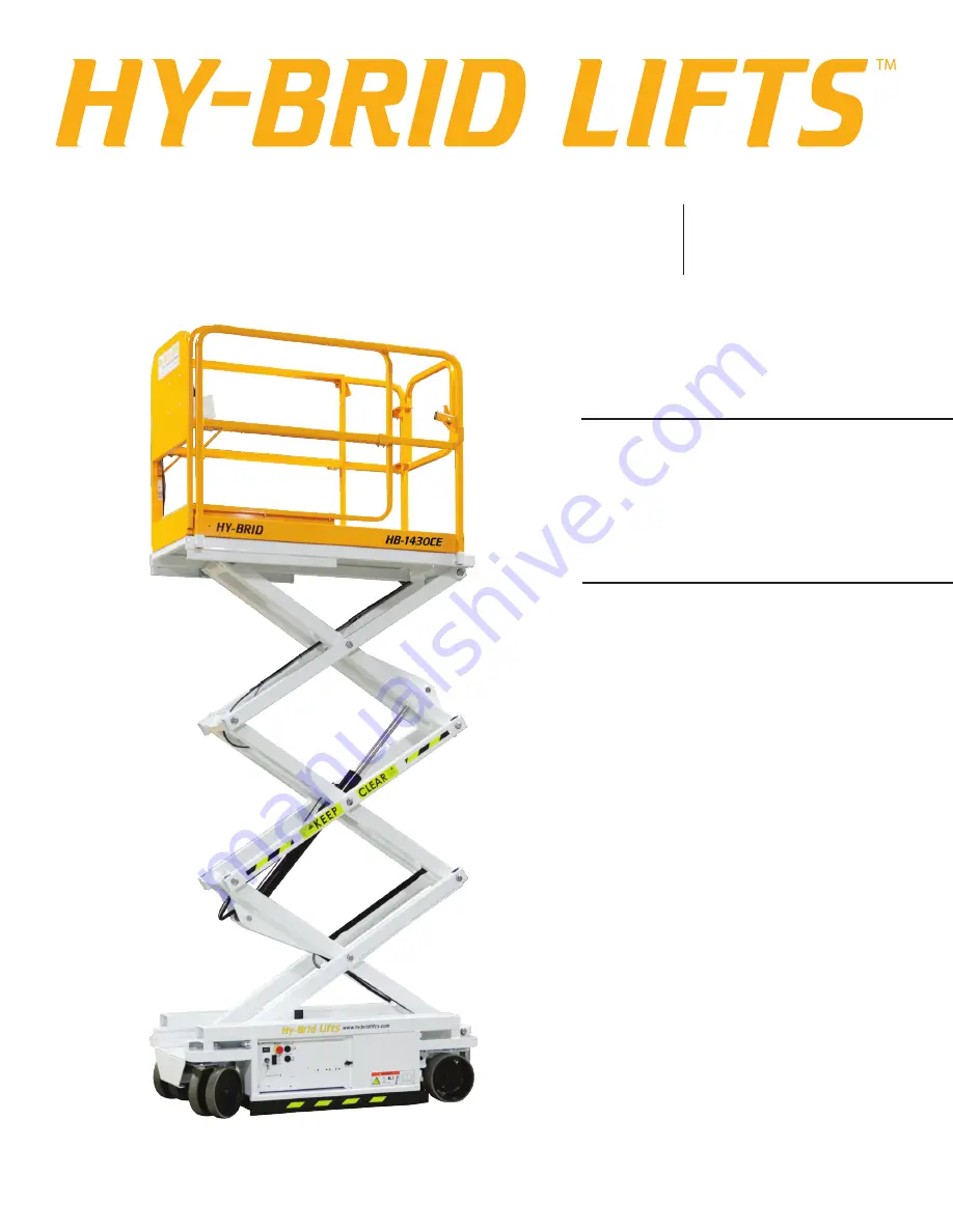
Page 1: ...BY CUSTOM EQUIPMENT LLC OPERATIONS SAFETY MANUAL SELF PROPELLED AERIAL WORK PLATFORM SUPO 713 REV A HB 1030CE HB 1430CE SERIES III ...

Page 2: ...PERATIONS SAFETY HB 1030CE HB 1430CE SUPO 713 REV A 2 If there is a question about application and or operation contact Custom Equipment LLC 2647 Hwy 175 Richfield WI 53076 U S A P 1 262 644 1300 F 1 262 644 1320 www hybridlifts com ...

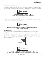
Page 3: ...UFACTURER IS PROHIBITED Fall protection notice The guardrail system around the perimeter of the platform is the fall protection system for self propelled elevating work platforms per the EN 280 Standard It is prohibited to use an Aerial Work Platform manufactured by Custom Equipment LLC With any portion or all of the guardrails removed Lanyard anchorage points on this type of equipment are not req...

Page 4: ...L DESCRIPTIONS 15 3 3 DECAL SYMBOLS 16 SECTION 4 TRANSPORT HANDLING STORAGE 19 4 1 PRELIMINARY UNPACKING INSTRUCTIONS AND DEALER INSPECTION 19 4 2 STORAGE 19 4 3 PREPARATION FOR TRANSPORT 19 4 4 LIFTING AND TIE DOWN POINTS 20 4 5 FORK LIFT POCKETS 20 SECTION 5 OPERATION 22 5 1 BEFORE YOU OPERATE 22 5 2 STARTUP SHUT DOWN 23 5 3 ERROR ALARMS 24 5 4 DRIVING AND STEERING 25 5 5 ELEVATING AND LOWERING ...

Page 5: ...ase 19 FIGURE 8 Tie Down Points Rear 20 FIGURE 9 Fork Pockets 20 FIGURE 10 Center of Gravity 21 FIGURE 11 Base Controls 22 FIGURE 12 Platform Controls 22 FIGURE 13 Main Power switch OFF 23 FIGURE 14 Main Power switch knob removed 23 FIGURE 15 Secure Location 23 FIGURE 16 Main Power switch 23 FIGURE 17 Slide Brake 26 FIGURE 18 Battery Charger LED Display 27 OPERATIONS SAFETY HB 1030CE HB 1430CE SUP...

Page 6: ...oles slopes debris floor or overhead obstructions surface wind and weather conditions or presence of unauthorized persons Vibration does not create significant hazards on this machine 1 2 CE DECLARATION OF CONFORMITY We hereby declare that the above mentioned machine has been assessed tested and approved in accordance with the requirements of the Machinery Directive 2006 42 EEC using the document ...

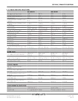
Page 7: ...ning Radius Inside 21 in 0 53 m 21 in 0 53 m Tire Size Solid Non Marking Front Rear 10 in 10 in 25 4 cm 25 4 cm 10 in 10 in 25 4 cm 25 4 cm RATED LOAD Lift Capacity Evenly Distributed 750 lb 2 Persons 340 2 kg 2 Persons 670 lb 2 Persons 304 kg 2 Persons Slide Out Deck Capacity 250 lb 1 Person 113 4 kg 1 Person 250 lbs 1 Person 113 4 kg 1 Person Horizontal Manual Force 90 lb 400 N 90 lb 400 N FLOOR...

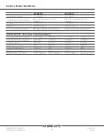
Page 8: ...rive Speed Platform Elevated 0 0 7 mph 0 31 m s 0 0 7 mph 0 31 m s Drive Speed Platform Lowered 0 2 5mph 0 1 18 m s 0 2 5mph 0 1 18m s Lift Lower Speed 15 16 sec 15 16 sec 21 18 sec 21 18 sec Hydraulic Pressure max 1300 psi 8963 kPa 1300 psi 8963 kPa Hydraulic Fluid Capacity 1 325 gal 5 38 L 1 325 gal 5 38 L Power System Voltage 24V DC 24V DC 24V DC 24V DC Batteries Deep Cycle Marine 2 12V Group 2...

Page 9: ... hazards on this machine An operator of any type of work platform is subject to certain hazards that cannot be protected by mechanical means It is therefore essential that operators be competent careful physically and mentally fit and thoroughly trained in safe operation of this machine Although Custom Equipment LLC conforms to specified EN 280 requirements it is the responsibility of the owner to...

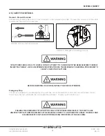
Page 10: ...chine is tilted more than 2 longitudinally or 1 5 laterally Elevating and driving functions are inhibited Lower the platform and move to a level surface Load Sensing An audible alarm sounds a light flashes and movement is inhibited when the load exceeds the rated load Remove the excess load before continuing operation Armguard When lowering the platform the platform will stop when the ends of the ...

Page 11: ... THE DECK EXTENSION Emergency Stop This lift is equipped with two emergency stop switches one at the platform control and one at the base control that when activated will render the unit inoperable until reset To reset pull the button out PUSHING THE EMERGENCY STOP BUTTON WILL APPLY BRAKES IMMEDIATELY THIS MAY CAUSE UNEXPECTED PLATFORM MOVEMENT AS THE MACHINE COMES TO A SUDDEN STOP BRACE YOURSELF ...

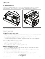
Page 12: ...r Use machine only for purposes for which it was intended Lift should never be used as a crane Do not exceed the load capabilities of the platform Distribute load evenly over platform floor area Never use unit as electrical grounds for arc welding Do not override any hydraulic mechanical or electrical safety devices Check job site for unsafe working conditions Watch out for others Keep others clea...

Page 13: ...machine from the platform Never belt or tie off to an adjacent structure Secure tools and materials Personnel must maintain a firm footing on the platform floor and work only within the platform area It is recommended to avoid sudden braking or steering Go slowly and leave more maneuvering room during cold weather operation Before operation ensure that the machine is properly serviced Do not use m...

Page 14: ...3 1 DECAL LOCATIONS SECTION 3 DECALS FIGURE 6 Decal Locations BY CUSTOM EQUIPMENT LLC OPERATIONS SAFETY HB 1030CE HB 1430CE SUPO 713 REV A 14 ...

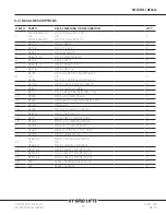
Page 15: ...2 DE747 DECAL BRAKE RELEASE NO TOW 1 13 DE751 DECAL E DOWN CABLE 1 14 DE736 DECAL WHL LOAD HB 1430CE S2 3 4 15 DE718 DECAL CE 2 16 DE752 DECAL CHARGER CORD EU 1 17 DE679 DECAL HYDR FLUID 1 18 DE777 DECAL BATT CHARGE DAILY 1 19 DE786 DECAL CTL LWR HBLGS3 CE 1 20 DE785 DECAL CTL UPR HBS4 ACT 1 21 DE649 DECAL CAPACITY TOOL TRAY 1 22 DE782 DECAL MADE IN USA 1 23 DE603 10 OR DE603 11 DECAL MODEL HB 103...

Page 16: ...rer s maintenance requirements contained in the operating and maintenance requirements contained in the operation and maintenance manual and the daily safety checklist Crushing Hazard Do not enter the space beneath the work platform or scissor structure unless the maintenance lock is in place Refer to Maintenance Manual Only qualified service personnel may service the machine Failure to comply wit...

Page 17: ...aratus You must allow for machine sway rock or sag and electrical lines swaying This machine does not provide protection from contact with or proximity to an electrically charged conductor You must maintain a clearance between any part of this machine or its load and any electrical apparatus Follow local power line regulations Death or serious injury will result from contact or inadequate clearanc...

Page 18: ...ion Capacity 1 Person Lanyard anchorage points are for work positioning restraints only not for fall protection Use of fall arrest systems attached to anchorage points on mobile equipment may cause machine to tip resulting in serious injury or death SECTION 3 DECALS BY CUSTOM EQUIPMENT LLC OPERATIONS SAFETY HB 1030CE HB 1430CE SUPO 713 REV A 18 ...

Page 19: ...RT Lower the work platform to the down position Bring the platform slide out extension into the retracted position and lock in place Turn the key switch to off position Check the entire machine for loose or unsecured items Remove any loose items from machine For winching or pushing manually release the parking brakes one for each drive motor at the rear of the machine Push both levers toward the f...

Page 20: ... LIFT POCKETS Fork lift pockets are provided from the front and back of the unit for loading and unloading A forklift from the side of the machine is not recommended Do not use a forklift underneath the machine from the back When moving machine with a forklift do not let machine slide along floor Bring forklift to a stop and then gently lower the machine FIGURE 8 Tie Down Points Rear FIGURE 9 Fork...

Page 21: ...is Y Axis HB 1030CE 31 in 73 cm 13 in 33 cm HB 1430CE 31 in 78 cm 15 5 in 39 cm SECTION 4 TRANSPORT HANDLING STORAGE FIGURE 10 Center of Gravity OPERATIONS SAFETY HB 1030CE HB 1430CE SUPO 713 REV A BY CUSTOM EQUIPMENT LLC 21 ...

Page 22: ...Battery Volt Meter 4 Up Down Rocker Switch Operation described as follows 5 Key Switch Operation described as follows 6 Hour Meter Displays operation hours 7 Emergency Stop Operation described in Safety Controls Section 8 Beeper See Safety Indicators Section for more information 9 Overload Light Item Control Indicator 1 Drive Enable Trigger Operation described as follows 2 Joystick Operation descr...

Page 23: ...n the stowed position using the constant three point contact method Follow all general rules and precautions stated in this manual When finished with the machine place the platform in the stowed position Park the machine on a level surface Carefully exit the platform using the constant three point contact method NEVER JUMP OFF PLATFORM Remove key from lower control panel to prevent unauthorized us...

Page 24: ...e scissor are 50mm apart Release the joystick enable look around all sides of the scissors to check for persons at risk Then continue lowering the platform Medium Pulse Machine Begins Elevating and Stops Pothole Guards Not Engaged Check for Obstruction Solid Machine will not drive Brakes are manually released Turn handle to engage brakes before using OR Battery charger is plugged in Unplug before ...

Page 25: ...ed in the center neutral position In the event of a machine failure the machine can be pushed by releasing the parking brake at the rear of the machine See Section 4 3 on pagepage 20 for brake release information 5 5 ELEVATING AND LOWERING Using Upper Platform Controls Use the key switch to on the lower contrls to select the platform controls To activate elevate lower function select elevate mode ...

Page 26: ...actorily with a minimum of service and repair Make checks at the stated intervals or more frequently if required by local operating conditions The following inspection checklists are included in this manual Pre Start required before operation at each work shift Pre Delivery Frequent Annual Required every 3 months after periods of storage and after any alterations or repairs The rated life of the m...

Page 27: ...at the power is on but there is no connection to a battery The charger must see approximately five 5 volts on a battery to deliver D C current This display indicates that power is on and that both outputs are delivering D C current to the batteries This display indicates that power is on and that both outputs are finished charging and are in a float maintenance mode A flashing red light indicates ...

Page 28: ...NTATIVE MAINTENANCE AT RECOMMENDED INTERVALS MAY RESULT IN THE UNIT BEING OPERATED WITH DEFECTS THAT MAY RESULT IN INJURY OR DEATH OF THE OPERATOR This unit is equipped with 12 volt AGM maintenance free batteries NOTE The surrounding temperature greatly affects the power reserve within a battery EXAMPLE A battery that is 100 charged at 80 F 27 C drops to 65 at 32 F 0 C At 0 F 18 C this battery wil...

Page 29: ...SECTION 5 OPERATION THIS PAGE WAS INTENTIONALLY LEFT BLANK OPERATIONS SAFETY HB 1030CE HB 1430CE SUPO 713 REV A BY CUSTOM EQUIPMENT LLC 29 ...

Page 30: ...ed models Thumb rocker steers right left For Counter Rotate Steering models Elevates lowers If so equipped horn sounds when button is pressed Base Controls Check all switches and push buttons for proper operation Emergency Stop Stops all movement For Actuator Steered models Key Switch On or Off For Counter Rotate Steering models Key Switch Selects Platform Control Ground Control or Off Up Down Roc...

Page 31: ...NOTES OPERATIONS SAFETY HB 1030CE HB 1430CE SUPO 713 REV A BY CUSTOM EQUIPMENT LLC 31 ...

Page 32: ...2647 Highway 175 Richfield WI 53076 U S A Tel 1 262 644 1300 Fax 1 262 644 1320 www hybridlifts com Service Customequipmentlifts com Hy Brid Lifts is a trademark of Custom Equipment LLC These machines comply with specified EN280 requirements Revision Date June 2016 Printed In The USA BY CUSTOM EQUIPMENT LLC ...

Reviews: