background image

Bedienungsanleitung 

(Originalanleitung) 

Operating Instructions  

(Translation of original 

instructions) 

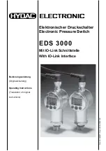
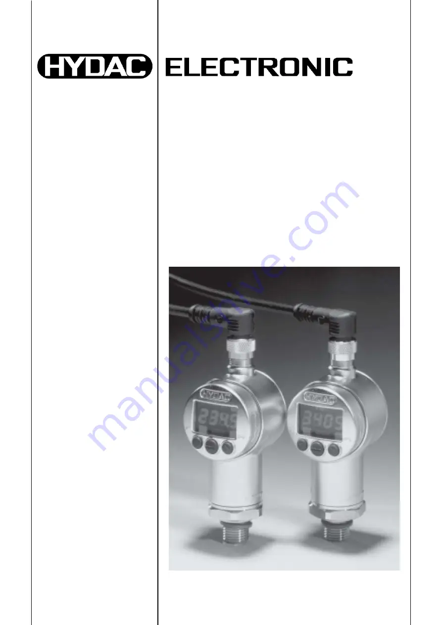
Elektronischer Druckschalter 
Electronic Pressure Switch 

EDS 3000 

Mit IO-Link Schnittstelle 

With IO-Link Interface 

M

at

 –N

r.

 66

98

97

 /

 S

ta

nd:

 2

0.

04.

20

20

 D

/E


Summary of Contents for EDS 3000

Page 1: ...iginalanleitung Operating Instructions Translation of original instructions Elektronischer Druckschalter Electronic Pressure Switch EDS 3000 Mit IO Link Schnittstelle With IO Link Interface Mat Nr 669897 Stand 20 04 2020 D E ...

Page 2: ...auswahl und Qualifikation Grundsätzliche Pflichten 7 4 5 Organisatorische Maßnahmen 8 5 Funktionen des EDS 3000 8 6 Montage 8 6 1 Allgemeine Montagehinweise 8 6 2 Zusätzliche Montagehinweise 9 7 Bedienelemente des EDS 3000 9 8 Betriebsarten 10 8 1 SIO Mode 10 8 2 SDCI Mode 10 9 Parametrierung 11 9 1 Allgemeines 11 9 2 Parametrierung im SDCI Mode 11 9 3 Parametrierung im SIO Mode 11 9 4 Parametrier...

Page 3: ...Spitzenwertes 19 15 Programmierfreigabe 20 15 1 Allgemeines 20 15 2 Ändern der Programmierfreigabe 20 16 Nullpunktkalibrierung 20 17 Fehlermeldungen 21 18 Anschlussbelegung 21 19 Technische Daten 22 19 1 EDS 3000 mit Keramik Sensorzelle Absolut und Relativdruck bis 16 bar 500 psi 22 19 2 EDS 3000 mit Dünnfilm DMS Sensorzelle Relativdruck ab 40 bar 1000 psi 24 19 3 Relevante Daten für IO Link 25 20...

Page 4: ... 04 2020 HYDAC ELECTRONIC GMBH Mat Nr 669897 22 Zubehör 29 22 1 Elektrischer Anschluss 29 22 2 Mechanischer Anschluss 29 23 Abkürzungsverzeichnis 31 24 Kontakt 32 25 Anhang Annex IODD Einstellparameter IODD Setting Parameters 33 ...

Page 5: ...tdecken Sie beim Lesen dieser Dokumentation Fehler oder haben weitere Anregungen und Hinweise so wenden Sie sich bitte an HYDAC ELECTRONIC GMBH Technische Dokumentation Hauptstraße 27 66128 Saarbrücken Deutschland Tel 49 0 6897 509 01 Fax 49 0 6897 509 1726 E Mail electronic hydac com Die Redaktion freut sich über Ihre Mitarbeit Aus der Praxis für die Praxis Diese Bedienungsanleitung einschließlic...

Page 6: ...er Haftungsausschluss gilt nicht bei Vorsatz und grober Fahrlässigkeit Er gilt ferner nicht für Mängel die arglistig verschwiegen wurden oder deren Abwesenheit garantiert wurde sowie bei schuldhafter Verletzung von Leben Körper und Gesundheit Sofern wir fahrlässig eine vertragswesentliche Pflicht verletzen ist unsere Haftung auf den vorhersehbaren Schaden begrenzt Ansprüche aus Produkthaftung blei...

Page 7: ...bau in eine Anlage Maschine Des Weiteren wurde die Konformität des Mess Systems hinsichtlich der EMV Richtlinie geprüft Die Inbetriebnahme des Mess Systems ist deshalb erst dann erlaubt wenn festgestellt wurde dass die Anlage Maschine in die das Mess System eingebaut werden soll den Bestimmungen der EG Maschinenrichtlinie der EG EMV Richtlinie den harmonisierten Normen Europanormen oder den entspr...

Page 8: ... 3000 Je nach Ausführung bietet das Gerät folgende Funktionen Unterstützt IO Link Spezifikation V1 1 und V1 0 Unterstützt SIO Modus Anzeige der Schaltzustände im SIO Modus Modusanzeige SIO oder SDCI Anpassung an die jeweilige Applikation durch spezifische Parametereinstellung Messwertanzeige des aktuellen Druckes in psi MPa bar Anzeige des Maximalwertes oder eines eingestellten Schaltpunktes Schal...

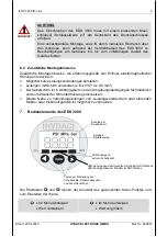
Page 9: ...dungen herstellen Leitungen mit Schirm verwenden z B LIYCY 4 x 0 5 mm Der Kabelschirm ist in Abhängigkeit von den Umgebungsbedingungen fachmännisch und zum Zweck der Störunterdrückung einzusetzen Direkte Nähe zu Verbindungsleitungen von Leistungsverbrauchern oder störenden Elektro oder Elektronikgeräten ist möglichst zu vermeiden 7 Bedienelemente des EDS 3000 Die Pfeiltasten und dienen der Auswahl...

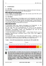
Page 10: ...4 Bit verwendet Die Anzahl der verwendeten Dezimalstellen hängt vom Messbereich ab und ist der Gerätebeschreibungsdatei IODD zu entnehmen 2 weitere Bits fungieren als Schaltbits BDC Binary Digital Channel die wie physische Transistorschalter parametriert werden können siehe hierzu Kapitel 9 Parametrierung Die Prozess Bits sind in einem Datenwort gemäß Tabelle 1 angeordnet Um den physikalischen Dru...

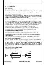
Page 11: ...hiedenen Produktausführungen Material nummern sind der entsprechenden IODD IO Device Description zu entnehmen Die Einstellparameter der IODD finden Sie in Kapitel 9 Parametrierung Die komplette IODD steht zum Download auf unserer Homepage zur Verfügung http www hydac com de de produkte sensorik show Material index html Produkte Sensorik Produktsuche Bei Eingabe der Materialnummer 9xxxxx erscheint ...

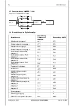
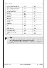
Page 12: ...t Ausgang 2 sp2 SP2 Rückschaltpunkt Ausgang 2 rp2 RP2 Druckfenster oberer Wert Ausgang 1 fk1 FH1 Druckfenster unterer Wert Ausgang 1 fl1 FL1 Druckfenster oberer Wert Ausgang 2 fk2 FH2 Druckfenster unterer Wert Ausgang 2 fl2 FL2 Erweiterte Funktionen ef EF Rücksetzen res RES Schaltverzögerungszeit Ausgang 1 ds1 dS1 Schaltverzögerungszeit Ausgang 2 ds2 dS2 Rückschaltverzögerungszeit Ausgang 1 dr1 dR...

Page 13: ...eit MPa mpa MPa Einheit psi psi psi Max Wert ki HI Fehleranzeige err ERR Display dis DIS Rücksetzen Ja yes Yes Nein no No Reset Max Wert rS kL rS HL Programmiersperre Pr6 PrG Nullpunktkalibrierung CALi cALi Neu nEU nEU HINWEISE Übersteigt der aktuelle Druck den Nenndruck des Gerätes so kann er nicht mehr angezeigt werden und die Anzeige beginnt zu blinken Liegt der aktuelle Druck unterhalb 0 6 des...

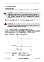
Page 14: ... Profile Specification kann bei HYDAC IO Link Sensoren eine Schalt und Rückschaltverzögerung parametriert werden ACHTUNG Bei Über bzw Unterschreiten des Messbereichs erfolgt eine Limitierung auf die jeweilige Messbereichsober bzw Untergrenze 11 1 1 Two Point Mode Einstellung auf Schaltpunkt SP Zu jedem Schaltausgang kann ein Schaltpunkt und ein Rückschaltpunkt eingestellt werden Der jeweilige Ausg...

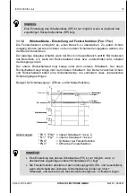
Page 15: ...eine Sicherheitszone die verhindert dass unerwünschte Schaltvorgänge erfolgen Beispiel für Schaltausgang 1 Öffner und Schließerfunktion Abkürzungen FH1 FH2 oberer Schaltwert 1 bzw 2 FL1 FL2 unterer Schaltwert 1 bzw 2 FNO Schließer bei Fensterfunktion FNC Öffner bei Fensterfunktion HINWEISE Eine Einstellung des oberen Schaltwertes FH ist nur möglich wenn er oberhalb des zugehörigen unteren Schaltwe...

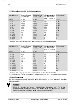
Page 16: ...on RP FL Obere Grenze von SP FH Mindestabstand zw RP und SP bzw FL und FH Schrittweite in psi in psi in psi in psi 0 15 0 15 15 0 15 0 05 0 30 0 30 30 0 3 0 05 0 50 0 5 50 0 5 0 1 14 75 13 0 75 1 0 0 2 0 150 1 5 150 1 5 0 5 0 250 2 5 250 2 5 0 5 0 500 5 500 5 1 0 1000 10 1000 10 2 0 3000 30 3000 30 5 0 6000 60 6000 60 10 0 9000 90 9000 90 20 Alle in der Tabelle angegebenen Bereiche sind im Raster ...

Page 17: ...nstellungen Zur Anpassung an die jeweilige Applikation kann das Verhalten des EDS 3000 über mehrere Einstellungen verändert werden Diese sind zu einem Menü zusammen gefasst 12 1 Hauptmenü Der Bereich wird nicht angezeigt wenn in Erweiterte Funktionen unter ou2 i oder u eingestellt ist ...

Page 18: ...18 EDS 3000 IO Link Stand 20 04 2020 HYDAC ELECTRONIC GMBH Mat Nr 669897 12 2 Erweiterte Funktionen Der Bereich wird nicht angezeigt wenn in Erweiterte Funktionen unter ou2 i oder u eingestellt ist ...

Page 19: ...ung wird das Menü automatisch beendet ohne dass eventuelle Änderungen wirksam werden 14 Rücksetzen des Spitzenwertes Der Spitzenwert des Druckes kann zurückgesetzt werden In den Erweiterten Funktionen die Taste betätigen bis der Menüpunkt rSHL erscheint mode Taste betätigen Mit auf YES setzen und mit der mode Taste quittieren Nun wird der Max Wert zurückgesetzt ...

Page 20: ...nstellung mit der mode Taste quittieren 16 Nullpunktkalibrierung Die Funktion Cali ermöglicht eine Nullpunktkalibrierung Der momentane Druck wird als neuer Nullpunkt gespeichert Dies ist im Bereich 3 des Gerätenenndruckes möglich In den Erweiterten Funktionen die Taste betätigen bis der Menüpunkt Cali erscheint mode Taste betätigen Mit auf YES setzen und mit der mode Taste quittieren In der Anzeig...

Page 21: ...e E 12 Bei den abgespeicherten Kalibrierdaten wurde ein Fehler erkannt Mögliche Ursachen sind starke elektromagnetische Störungen oder ein Bauteildefekt Abhilfe Gerät von der Versorgungsspannung trennen und wieder verbinden Steht der Fehler weiter an muss das Gerät zur Neukalibrierung oder Reparatur ins Werk zurück E 21 Es wurde ein Kommunikationsfehler innerhalb des Gerätes erkannt Mögliche Ursac...

Page 22: ...Sensorzelle Keramik Dichtung FPM EPDM gemäß Typenschlüssel Ausgangsgrößen Ausgangssignale Ausgang 1 Schaltausgang Ausgang 2 konfigurierbar als Schaltausgang oder Analogausgang Schaltausgang PNP Transistorschaltausgänge Schaltstrom SP1 max 0 1 A SP2 max 0 25 A Schaltzyklen 100 Millionen Analogausgang zulässige Bürde wählbar 4 20 mA Bürde max 500 Ω 0 10 V Bürde min 1 kΩ Genauigkeit nach DIN 16086 Gr...

Page 23: ...stwelligkeit Versorgungsspannung 5 Stromaufnahme 0 535 A mit aktiven Schaltausgängen 35 mA mit inaktiven Schaltausgängen 55 mA mit inaktivem Schaltausgang und Analogausgang Anzeige 4 stellig LED 7 Segment rot Zeichenhöhe 7 mm Gewicht ca 120 g Anm Überspannungs Übersteuerungsschutz Lastkurzschlussfestigkeit sind vorhanden FS Full Scale bezogen auf den vollen Messbereich ...

Page 24: ...nkteinstellung 0 5 FS typ 1 FS max Temperaturdrift Typ Nullpunkt Max 0 015 FS C 0 0085 FS F 0 025 FS C 0 014 FS F Temperaturdrift Typ Spanne Max 0 015 FS C 0 0085 FS F 0 025 FS C 0 014 FS F Wiederholbarkeit 0 25 FS max Reaktionszeit 10 ms Langzeitdrift 0 3 FS typ Jahr Umgebungsbedingungen Kompensierter Temperaturbereich 10 70 C 14 158º F Betriebstemperaturbereich 25 80 C 13 176º F Lagertemperaturb...

Page 25: ...e Communication IO Link Revision V1 1 Unterstützung V1 0 Transmission Rate Baudrate 38 4 kBaud COM2 Minimum Cycle Time 2 5 ms Prozessdatenbreite 16 Bit SIO Mode Supported Yes M Sequence Capability PREOPERATE TYPE_0 with 1 octet on request data OPERATE TYPE_2_2 with 1 octet on request data ISDU supported Verbindung mit ungeschirmter Standard Sensorleitung bis zu einer maximalen Leitungslänge von 20...

Page 26: ...Druckbereich in psi 9 Einschraubloch DIN 3852 G1 4 nur in Verbindung mit Druckbereich in bar Anschlussart elektrisch 6 Gerätestecker M12x1 4 pol ohne Kupplungsdose Ausgang F31 IO Link Schnittstelle Druckbereich Ausführung 1 Keramik absolut In bar 0001 02 5 In psi 0015 0050 Ausführung 3 Keramik relativ In bar 0001 1 1 bar 01 0 02 5 06 0 0010 0016 In psi 0015 0030 0050 0150 0250 0500 0089 14 75 psi ...

Page 27: ...1 4 A ISO 1179 2 DIN 3852 nur in Verbindung mit Druckbereich in bar 7 9 16 18 UNF 2A SAE6 Außengewinde nur in Verbindung mit Druckbereich in psi 9 Einschraubloch DIN 3852 G1 4 nur in Verbindung mit Druckbereich in bar Anschlussart elektrisch 6 Gerätestecker M12x1 4 pol ohne Kupplungsdose Ausgang F31 IO Link Schnittstelle Druckbereich In bar 0040 0100 0250 0400 0600 In psi 1000 3000 6000 9000 Modif...

Page 28: ...28 EDS 3000 IO Link Stand 20 04 2020 HYDAC ELECTRONIC GMBH Mat Nr 669897 21 Geräteabmessungen ...

Page 29: ... 4 pol Kupplungsdose abgewinkelt mit 2 m Leitung Material Nr 6006790 ZBE 06 05 4 pol Kupplungsdose abgewinkelt mit 5 m Leitung Material Nr 6006789 Farbkennung Pin 1 braun Pin 2 weiß Pin 3 blau Pin 4 schwarz 22 2 Mechanischer Anschluss ZBM 3000 Schelle zur Wandbefestigung anschraubbar Werkstoff Unterteil TPE Santoprene 10187 Oberteil Bandstahl DIN 95381 1 4571 Material Nr 3184630 ...

Page 30: ...chelle zur Wandbefestigung anschweißbar Werkstoff Schweißlasche QSTE340TM galvanischer Überzug EN 12329 FE ZN8 B Unterteil TPE Santoprene 10187 Oberteil Bandstahl DIN 95381 1 4571 Material Nr 3184632 ZBM 3200 Spritzwasserschutz Werkstoff Elastollan S60 A15 SPF 000 Material Nr 3201919 ...

Page 31: ...FNC Fensterfunktion Öffner FNO Fensterfunktion Schließer FS Full Scale H HNC Hystesefunktion Öffner HNO Hysteresefunktion Schließer Hyst Hysterese I IODD IO Device Description ISDU Indexed Service Data Unit O OU Ausgangsfunktion R RP Rückschaltpunkt S SDCI Single drop digital communication interface SIO Standard IO Modus SP Schaltpunkt SSC Schaltsignalkanal ...

Page 32: ...en der HYDAC Service zur Verfügung HYDAC SERVICE GMBH Hauptstr 27 D 66128 Saarbrücken Germany Tel 49 0 6897 509 1936 Fax 49 0 6897 509 1933 Anmerkung Die Angaben in dieser Bedienungsanleitung beziehen sich auf die beschriebenen Betriebs bedingungen und Einsatzfälle Bei abweichenden Einsatzfällen und oder Betriebsbedingungen wenden Sie sich bitte an die entsprechende Fachabteilung Bei technischen F...

Page 33: ...ial index ht ml Products Sensors Product search When entering the material number 9xxxxx the corresponding ZIP file appears The IODD finder can also be used as a further data source for IODDs https ioddfinder io link com productvariants vendorName 22HYDA C 20ELECTRONIC 20GmbH 22 EDS 3446 F31 0250 000 Vendor ID 348 0x015c Vendor Name HYDAC ELECTRONIC GMBH Vendor Text Hauptstr 27 D 66128 Saarbrücken...

Page 34: ...ubindex bit offset data type allowed values default value mod other var name description 1 24 8 bit UInteger 0 Default 1 Inverted 0 V_PrimaryValueSp1 Switch Point Logic NO NC 2 16 8 bit UInteger 2 Window 3 Two Point 3 V_PrimaryValueSp1 Switch Point Mode 3 0 16 bit UInteger 0 V_PrimaryValueSp1 Switch Point Hysteresis octet 0 1 2 3 bit offset 31 24 23 16 15 8 7 0 subindex 1 2 3 3 element bit 7 0 7 0...

Page 35: ...x 1 1 2 2 element bit 15 8 7 0 15 8 7 0 Variable BDC2 Behavior index 63 id V_Bdc2Behavior data type 32 bit Record subindex access not supported access rights rw modifies other variables excluded from data storage subindex bit offset data type allowed values default value mod other var name description 1 24 8 bit UInteger 0 Default 1 Inverted 0 V_PrimaryValueSp2 Switch Point Logic NO NC 2 16 8 bit ...

Page 36: ...bindex 5 5 6 6 6 6 element bit 15 8 7 0 31 24 23 16 15 8 7 0 Variable Primary Value SP2 index 65 id V_PrimaryValueSp2 data type 112 bit Record subindex access not supported access rights rw modifies other variables subindex bit offset data type allowed values default value mod other var name description 1 104 8 bit UInteger 0 Normally Open 1 Normally Closed 0 V_Bdc2Behavior Direction 2 96 8 bit UI...

Page 37: ...es 0 Primary Value SP1 BDC1 default value 0 access rights rw octet 0 bit offset 7 0 element bit 7 0 Variable Q2 QA Mapping index 74 id V_Q2QAMapping data type 24 bit Record subindex access not supported access rights rw subindex bit offset data type allowed values default value mod other var name description 1 16 8 bit UInteger 0 Primary Value SP2 BDC2 0 Output Source 2 8 8 bit UInteger 0 digital ...

Page 38: ...teger 0 Lower Value 2 40 16 bit Integer 2500 Upper Value 3 32 8 bit Integer 1 Decimals 4 0 4 octet String UTF 8 bar Unit Variable Primary Value index 84 id V_PrimaryValue data type 24 bit Record subindex access not supported access rights ro dynamic subindex bit offset data type allowed values default value mod other var name description 1 8 16 bit Integer 0 Process Value 2 3 Boolean true Not Avai...

Page 39: ...access rights ro dynamic subindex bit offset data type allowed values default value mod other var name description 1 8 16 bit Integer 0 Process Value 2 2 Boolean false Overflow Octet 0 bit offset 23 22 21 20 19 18 17 16 subindex 1 element bit 15 14 13 12 11 10 9 8 Octet 1 bit offset 15 14 13 12 11 10 9 8 subindex 1 element bit 7 6 5 4 3 2 1 0 Octet 2 bit offset 7 6 5 4 3 2 1 0 subindex 2 ...

Page 40: ...8 0x80 51 0x33 Parameter length overrun Written parameter length is above its predefined length 128 0x80 52 0x34 Parameter length underrun Written parameter length is below its predefined length 128 0x80 53 0x35 Function not available Written command is not supported by the device application 128 0x80 54 0x36 Function temporarily unavailable Written command is not available due to the current stat...

Page 41: ...porarily disabled 36032 0x8cc0 Warning Primary value out of range Primary value is below or above its valid range and limited to the corresponding lower or upper value 36350 0x8dfe Error System Test Event 1 IO Link V1 1 system test event 1 event appears by setting index 2 to value 240 event disappears by setting index 2 to value 241 36351 0x8dff Error System Test Event 2 IO Link V1 1 system test e...

Page 42: ......

Page 43: ...Instruction manual Translation of original instructions Electronic Pressure Switch EDS 3000 with IO Link Interface Part no 669897 Edition 2020 04 20 E ...

Page 44: ...amental obligations 7 4 5 Organisational measures 8 5 Functions of the EDS 3000 8 6 Installation 8 6 1 General installation notes 8 6 2 Additional installation instructions 9 7 Control elements of the EDS 3000 9 8 Operation modes 10 8 1 SIO mode 10 8 2 SDCI mode 10 9 Parameterisation 11 9 1 General overview 11 9 2 Parameterisation in SDCI mode 11 9 3 Parameterisation in SIO Mode 11 9 4 Parameteris...

Page 45: ...5 Program enable 20 15 1 General overview 20 15 2 Changing the Programming Enable 20 16 Offset calibration 20 17 Error Messages 21 18 PIN connection 21 19 Technical details 22 19 1 EDS 3000 with ceramic sensor cell absolute and relative pressure up to 16 bar 500 psi 22 19 2 EDS 3000 with thin film strain gauge relative pressure from 40 bar 1000 psi 24 19 3 Relevant data for IO Link 25 20 Model cod...

Page 46: ...020 HYDAC ELECTRONIC GMBH Part no 669897 22 Equipment 29 22 1 Electrical connection 29 22 2 Mechanical connection 29 23 List of abbreviations 31 24 Contact information 32 25 Anhang Annex IODD Einstellparameter IODD Setting Parameters 33 ...

Page 47: ... illustrations and dimensions are therefore possible If you discover errors while reading the documentation or have additional suggestions or tips please contact us at HYDAC ELECTRONIC GMBH Technical documentation Hauptstr 27 66128 Saarbruecken Germany Phone 49 0 6897 509 01 Fax 49 0 6897 509 1726 E Mail electronic hydac com We look forward to receiving your input Putting experience into practice ...

Page 48: ...ion of liability does not apply in cases of intent and gross negligence Moreover it does not apply to defects which have been deceitfully concealed or whose absence has been guaranteed nor in cases of culpable harm to life physical injury and damage to health If we negligently breach any material contractual obligation our liability shall be limited to foreseeable damage Claims due to the Product ...

Page 49: ... to be a machine part for the installation into a system machine Moreover the conformity of the measuring system was investigated in respect of the EMC Directive It is therefore only permitted to start up the measuring system if it has been established that the system machine into which the measuring system is to be fitted satisfies the provisions of the EC Machinery Directive the EC EMC Directive...

Page 50: ...s the following functions IO Link specifications V1 1 and V1 0 are supported Supports SIO mode Display of the switching states in SIO mode Mode display SIO or SDCI Adaptation to the corresponding application using specific parameter settings Display of the actual pressure in psi MPa bar Display of the maximum value or of a pre set switch point Switching of the switching outputs in accordance with ...

Page 51: ...sible Use shielded cabling e g LIYCY 4 x 0 5 mm The cable shielding must be fitted by qualified personnel subject to the environmental conditions and with the aim of suppressing interference Keep the instrument well away from the electrical supply lines of power equipment as well as from any electrical or electronic equipment causing interference 7 Control elements of the EDS 3000 The and arrow ke...

Page 52: ...ss data value The number of decimal places used is based on the measuring range and can be taken from the device description file IODD 2 further bits function as switching bits BDC Binary digital channel which can be parameterised just as physical transistor switches please see chapter 9 Parameterisation The process bits are arranged in one data word in accordance with Table 1 In order to receive ...

Page 53: ...oduct versions part numbers please refer to the corresponding IODD IO Device Description The configuration parameters of the IODD can be found in chapter 9 Parameterisation You will find the link for download of the IODD on our homepage at http www hydac com uk en products sensors show Material Index html Products Sensors Produkt search Entering the part number 9xxxxx the corresponding ZIP file ap...

Page 54: ...tput 1 rp1 RP1 Switch point output 2 sp2 SP2 Switch back point output 2 rp2 RP2 Pressure window upper value port 1 fk1 FH1 Pressure window lower value port 1 fl1 FL1 Pressure window upper value port 2 fk2 FH2 Pressure window lower value port 2 fl2 FL2 Add on functions ef EF Reset res RES Switch delay time port 1 ds1 dS1 Switch delay time port 2 ds2 dS2 Switch back delay time output 1 dr1 dR1 Switc...

Page 55: ...bar bar bar Unit in MPa mpa MPa Unit in psi psi psi Max value ki HI Error indication err ERR Display dis DIS Reset Yes Yes Yes No no No Reset max value rS kL rS HL Programming disable Pr6 PrG Offset calibration CALi cALi New nEU nEU Notes If the current pressure exceeds the device s nominal pressure it can no longer be displayed and the display begins to flash If the actual pressure is less than 0...

Page 56: ...ch back delay can be set in HYDAC IO Link sensors ATTENTION Exceeding or falling below the measuring range leads to a limitation to the corresponding upper or lower limit of the measuring range 11 1 1 Two point mode Switch point setting SP One switch point and one switch back point can be set for each switching output The particular output will switch when the pre set switch point is reached and t...

Page 57: ...hing output 1 N C and N O function Abbreviations FH1 FH2 upper switch value 1 upper switch value 2 FL1 FL2 lower switch value 1 lower switch value 2 FNO N O when window function is active FNC N C when window function is active Notes Setting the upper switch value FH is only possible if it lies above the lower switch value FL The window function only works properly switching on and off if all switc...

Page 58: ... of RP FL Upper limit of SP FH Minimum difference betw RP and SP or FL and FH Increment in psi in psi in psi in psi 0 15 0 15 15 0 15 0 05 0 30 0 30 30 0 3 0 05 0 50 0 5 50 0 5 0 1 14 75 13 0 75 1 0 0 2 0 150 1 5 150 1 5 0 5 0 250 2 5 250 2 5 0 5 0 500 5 500 5 1 0 1000 10 1000 10 2 0 3000 30 3000 30 5 0 6000 60 6000 60 10 0 9000 90 9000 90 20 All ranges shown in the table can be adjusted by the in...

Page 59: ... 12 Basic Settings The EDS 3000 can be adapted to suit the particular application as required by changing multiple settings These settings are combined in a menu 12 1 Main menu The range is not displayed if i or u is pre set under ou2 in the extended functions Add on functions ...

Page 60: ...18 EDS 3000 IO Link Edition 20 04 2020 HYDAC ELECTRONIC GMBH Part no 669897 12 2 Add on functions The range is not displayed if i or u is pre set under ou2 in the extended functions ...

Page 61: ...approx 60 seconds the menu closes automatically and any changes that may have been made will not be saved 14 Resetting the peak value The pressure peak value can be reset In the extended functions menu please press the key until rSHL appears Press the mode key Press to select YES and confirm by pressing the mode key The maximum value is set back ...

Page 62: ...Offset calibration The function Cali enables the sensor offset calibration The current pressure is saved as the new offset This is possible in the range of 3 of the instrument rated pressure In the extended functions menu please press the key until Cali appears Press the mode key Press to select YES and confirm by pressing the mode key neW appears in the display when a calibration has been carried...

Page 63: ...ning E 12 An error was detected in the saved calibration data Possible causes are strong electromagnetic interference or a defective component Action Disconnect then reconnect the supply voltage to the instrument If the error persists the instrument must be returned to the factory for recalibration or repair E 21 A communication error within the unit has been detected Possible causes are strong el...

Page 64: ...onnection Stainless steel Sensor cell Ceramic Seal FPM EPDM as per model code Output variables Output signals Output 1 Switching output Output 2 can be configured as switching output or as analogue output switching output PNP transistor outputs Switching current SP1 max 0 1 A SP2 max 0 25 A Switching cycles 100 million Analogue output permitted load resistance selectable 4 20 mA load resistance ma...

Page 65: ...e of supply voltage 5 Current consumption 0 535 A with active switching outputs 35 mA with inactive switching outputs 55 mA with inactive switching output and analogue output Display 4 digit LED 7 segment red height of digits 7 mm Weight approx 120 g Note Excess voltage override protection and short circuit protection are provided FS Full Scale relative to complete measuring range ...

Page 66: ...racy acc to DIN 16086 Max setting 0 5 FS typ 1 FS max Temperature drift typ Offset max 0 015 FS C 0 0085 FS F 0 025 FS C 0 014 FS F Temperature drift typ Range max 0 015 FS C 0 0085 FS F 0 025 FS C 0 014 FS F Repeatability 0 25 FS max Reaction time 10 ms Long term drift 0 3 FS typ year Environmental Conditions Compensated temperature range 10 70 C 14 158º F Operating temperature range 25 80 C 13 1...

Page 67: ...cal User Interface Communication IO Link revision V1 1 support V1 0 Transmission Rate Baud rate 38 4 kBaud COM2 Minimum cycle time 2 5 ms Process data width 16 bit SIO Mode Supported Yes M Sequence Capability PREOPERATE TYPE_0 with 1 octet on request data OPERATE TYPE_2_2 with 1 octet on request data ISDU supported Connection with unscreened standard sensor line possible up to a max line length of...

Page 68: ...essure range in psi 9 Threaded port DIN 3852 G1 4 only in conjunction with pressure range in bar Electrical connection 6 Male M12x1 4 pole mating connector not supplied Output F31 IO Link interface Pressure range Design 1 ceramic absolute In bar 0001 02 5 In psi 0015 0050 Design 3 ceramic relative In bar 0001 1 1 bar 01 0 02 5 06 0 0010 0016 In psi 0015 0030 0050 0150 0250 0500 0089 14 75 psi Modi...

Page 69: ... 4 A ISO 1179 2 DIN 3852 only in conjunction with pressure range in bar 7 9 16 18 UNF 2A SAE6 male thread only in conjunction with pressure range in psi 9 Threaded port DIN 3852 G1 4 only in conjunction with pressure range in bar Electrical connection 6 Male M12x1 4 pole mating connector not supplied Output F31 IO Link interface Pressure range In bar 0040 0100 0250 0400 0600 In psi 1000 3000 6000 ...

Page 70: ...28 EDS 3000 IO Link Edition 20 04 2020 HYDAC ELECTRONIC GMBH Part no 669897 21 Dimensions Display adjustable 270 Housing adjustable 340 6hex SW27 Diameter connector M12x1 4 pole 6hex SW27 ...

Page 71: ...e Mating connector right angle with 2 m cable Part No 6006790 ZBE 06 05 4 pole Mating connector right angle with 5 m cable Part No 6006789 Colour code Pin 1 brown Pin 2 white Pin 3 blue Pin 4 black 22 2 Mechanical connection ZBM 3000 Clamp for wall mounting screw type fitting Material of lower section TPE Santoprene 10187 Material of top section steel strip DIN 95381 1 4571 Part No 3184630 ...

Page 72: ...for wall mounting weld type fitting Material of welding bridge QSTE340TM zinc coating EN 12329 FE ZN8 B Material of lower section TPE Santoprene 10187 Material of top section Steel strip DIN 95381 1 4571 Part No 3184632 ZBM 3200 Splash guard Material Elastollan S60 A15 SPF 000 Part no 3201919 ...

Page 73: ...e FNC Window function N C FNO Window function N O FS Full Scale H HNC Hysteresis function N C HNO Hysteresis function N O Hyst Hysteresis I IODD IO Device Description ISDU Indexed Service Data Unit O OU Output function R RP Switch back point S SDCI Single drop digital communication interface SIO Standard IO mode SP Switch point SSC Switching signal channel ...

Page 74: ...ing repairs please contact HYDAC Service HYDAC SERVICE GMBH Hauptstr 27 D 66128 Saarbruecken Germany Phone 49 0 6897 509 1936 Fax 49 0 6897 509 1933 Note The information in this operating manual relates to the operating conditions and applications described For applications or operating conditions not described please contact the relevant technical department If you have any questions suggestions ...

Page 75: ...rial index ht ml Products Sensors Product search When entering the material number 9xxxxx the corresponding ZIP file appears The IODD finder can also be used as a further data source for IODDs https ioddfinder io link com productvariants vendorName 22HYDA C 20ELECTRONIC 20GmbH 22 EDS 3446 F31 0250 000 Vendor ID 348 0x015c Vendor Name HYDAC ELECTRONIC GMBH Vendor Text Hauptstr 27 D 66128 Saarbrücke...

Page 76: ... subindex bit offset data type allowed values default value mod other var name description 1 24 8 bit UInteger 0 Default 1 Inverted 0 V_PrimaryValueSp1 Switch Point Logic NO NC 2 16 8 bit UInteger 2 Window 3 Two Point 3 V_PrimaryValueSp1 Switch Point Mode 3 0 16 bit UInteger 0 V_PrimaryValueSp1 Switch Point Hysteresis octet 0 1 2 3 bit offset 31 24 23 16 15 8 7 0 subindex 1 2 3 3 element bit 7 0 7...

Page 77: ...dex 1 1 2 2 element bit 15 8 7 0 15 8 7 0 Variable BDC2 Behavior index 63 id V_Bdc2Behavior data type 32 bit Record subindex access not supported access rights rw modifies other variables excluded from data storage subindex bit offset data type allowed values default value mod other var name description 1 24 8 bit UInteger 0 Default 1 Inverted 0 V_PrimaryValueSp2 Switch Point Logic NO NC 2 16 8 bi...

Page 78: ...ubindex 5 5 6 6 6 6 element bit 15 8 7 0 31 24 23 16 15 8 7 0 Variable Primary Value SP2 index 65 id V_PrimaryValueSp2 data type 112 bit Record subindex access not supported access rights rw modifies other variables subindex bit offset data type allowed values default value mod other var name description 1 104 8 bit UInteger 0 Normally Open 1 Normally Closed 0 V_Bdc2Behavior Direction 2 96 8 bit U...

Page 79: ...lues 0 Primary Value SP1 BDC1 default value 0 access rights rw octet 0 bit offset 7 0 element bit 7 0 Variable Q2 QA Mapping index 74 id V_Q2QAMapping data type 24 bit Record subindex access not supported access rights rw subindex bit offset data type allowed values default value mod other var name description 1 16 8 bit UInteger 0 Primary Value SP2 BDC2 0 Output Source 2 8 8 bit UInteger 0 digita...

Page 80: ...Integer 0 Lower Value 2 40 16 bit Integer 2500 Upper Value 3 32 8 bit Integer 1 Decimals 4 0 4 octet String UTF 8 bar Unit Variable Primary Value index 84 id V_PrimaryValue data type 24 bit Record subindex access not supported access rights ro dynamic subindex bit offset data type allowed values default value mod other var name description 1 8 16 bit Integer 0 Process Value 2 3 Boolean true Not Av...

Page 81: ... access rights ro dynamic subindex bit offset data type allowed values default value mod other var name description 1 8 16 bit Integer 0 Process Value 2 2 Boolean false Overflow Octet 0 bit offset 23 22 21 20 19 18 17 16 subindex 1 element bit 15 14 13 12 11 10 9 8 Octet 1 bit offset 15 14 13 12 11 10 9 8 subindex 1 element bit 7 6 5 4 3 2 1 0 Octet 2 bit offset 7 6 5 4 3 2 1 0 subindex 2 ...

Page 82: ...128 0x80 51 0x33 Parameter length overrun Written parameter length is above its predefined length 128 0x80 52 0x34 Parameter length underrun Written parameter length is below its predefined length 128 0x80 53 0x35 Function not available Written command is not supported by the device application 128 0x80 54 0x36 Function temporarily unavailable Written command is not available due to the current st...

Page 83: ...mporarily disabled 36032 0x8cc0 Warning Primary value out of range Primary value is below or above its valid range and limited to the corresponding lower or upper value 36350 0x8dfe Error System Test Event 1 IO Link V1 1 system test event 1 event appears by setting index 2 to value 240 event disappears by setting index 2 to value 241 36351 0x8dff Error System Test Event 2 IO Link V1 1 system test ...

Reviews: