background image

DOE

Compliant

K

GL SERIES

 - INS

T

ALLA

TION AND OPERA

TION MANU

AL - V0

Summary of Contents for KGL SERIES

Page 1: ...DOE Compliant KGL SERIES INSTALLATION AND OPERATION MANUAL V0 ...

Page 2: ...ORPORATION 5659 Royalmount Ave Montreal QC Canada H4P 2P9 Telephone 514 737 9701 Toll Free Telephone 888 275 4538 Fax 514 342 3854 Toll Free Fax 877 453 8832 Email sales mvpgroupcorp com Website www mvpgroupcorp com ...

Page 3: ...t 50 3 Refrigeration 54 3 1 Self contained refrigeration equipment and defrost 54 3 2 Refrigeration loads remotes only 56 4 Electrical 56 4 1 Electrical specifications data 56 4 3 Electrical diagrams 58 4 4 Electronic controller 90 5 Maintenance 93 5 1 Cleaning 93 5 2 Shelf removing adjustment 94 5 3 Light substitution 94 5 4 Panels and protection grille removal 95 5 5 Condenser cleaning 96 5 6 Ev...

Page 4: ...4 This page has been left blank intentionally ...

Page 5: ...stem KGL RS 40 S AAA BB CC D AAA BB CC D Model variation RS Rear doors and electrical shutter OF Open front OS Open front and electrical shutter DL Open front and rear doors RM Rear doors and manual shutter Length 40 50 60 Type of Unit S Self Contained R Remote Basic model ...

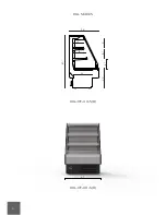
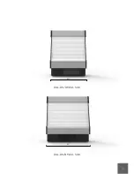
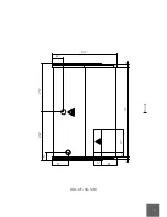
Page 6: ...6 34 60 12 16 11 12 10 23 22 KGL SERIES KGL OF XX S R 41 KGL OF 40 S R ...

Page 7: ...7 50 61 KGL OF 50 S R KGL OF 60 S R ...

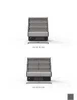
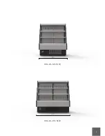
Page 8: ...8 KGL RS RM XX S R KGL RS RM 40 S R 41 36 60 12 16 11 12 10 23 23 ...

Page 9: ...9 KGL RS RM 50 S R KGL RS RM 60 S R 50 61 ...

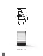
Page 10: ...10 KGL DL XX S R 36 60 12 16 11 12 10 23 23 KGL DL 40 S R 41 ...

Page 11: ...1 1 KGL DL 50 S R 50 KGL DL 60 S R 61 ...

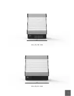
Page 12: ...12 KGL OS XX S R 34 12 16 65 22 23 12 10 11 KGL OS 40 S R 41 ...

Page 13: ...13 KGL OS 50 S R 50 KGL OS 60 S R 61 ...

Page 14: ...14 KGL OF 40 S R Front 3 2 8 5 9 12 34 21 6 2 38 5 21 Implantation Drain outlet Electrical board Refrigeration piping ...

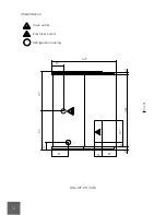
Page 15: ...15 Front KGL OF 50 S R 34 6 26 25 5 8 9 5 3 2 12 47 2 ...

Page 16: ...16 KGL OF 60 S R 34 6 31 31 5 3 2 12 57 2 8 9 5 Front ...

Page 17: ...17 KGL RS RM 40 S R 34 6 26 25 5 8 9 5 3 2 8 38 2 4 2 Drain outlet Electrical board Refrigeration piping Electrical wiring Front ...

Page 18: ...18 KGL RS RM 50 S R 34 6 26 25 5 8 9 5 3 2 12 47 2 4 2 Front ...

Page 19: ...19 KGL RS RM 60 S R 34 6 31 31 5 3 2 12 57 2 8 9 5 4 2 Front ...

Page 20: ...20 KGL DL 40 S R 34 6 21 21 5 8 9 5 3 2 8 38 2 Drain outlet Electrical board Refrigeration piping Front ...

Page 21: ...21 KGL DL 50 S R 34 6 25 26 5 8 9 5 3 2 12 47 2 Front ...

Page 22: ...22 KGL DL 60 S R 34 6 31 31 5 8 9 5 3 2 12 57 2 Front ...

Page 23: ...23 KGL OS 40 S R 34 6 21 21 5 8 9 5 3 2 12 2 3 2 38 Drain outlet Electrical board Refrigeration piping Electrical wiring Front ...

Page 24: ...24 KGL OS 50 S R 34 6 25 26 5 8 9 5 3 2 12 2 3 7 37 Front ...

Page 25: ...25 KGL OS 60 S R 34 6 31 31 5 8 9 5 3 2 12 57 2 12 3 Front ...

Page 26: ...4 x 513 4 50 x 591 4 x 565 16 607 16 x 6415 16 x 61 403 4 x 591 4 x 3513 16 50 x 591 4 x 3513 16 607 16 x 591 4 x 3513 16 403 4 x 6415 16 x 513 4 50 x 6415 16 x 565 16 607 16 x 6415 16 x 61 KGL OF 40 S R KGL OF 50 S R KGL OF 60 S R KGL DL 40 S R KGL DL 50 S R KGL DL 60 S R KGL OS 40 S R KGL OS 50 S R KGL OS 60 S R KGL RS RM 40 S R KGL RS RM 50 S R KGL RS RM 60 S R 2 Getting started with your KGL s...

Page 27: ...ries with shutter must be handled carefully Open and close shutter only when needed Models to be positioned against a wall keep a safe distance of 23 8 This equipment should be handled by a qualified technician 2 2 Uncrating All operations must be done carefully All plastic protective films must be removed before using the equipment for the first time 2 1 ...

Page 28: ... are sent out HYDRA KOOL doesn t take responsibility for damage between factory and client Possible damage on the unit must be checked to file a claim near the transportation company The unit must be checked in the following points Exterior panels Doors Shelves Glasses Paint job Door handles Base structure Shutter ...

Page 29: ...ON NE PAS OUVRIR MANUELLEMENT EN CAS DE PANNE ELECTRIQUE SUIVRE LES INSTRUCTIONS D INSTAL LATION ET DE FONCTIONNEMENT DU MODE D EMPLOI CAUTION FOR THE SHUTTER CORRECT OPEN ING AND CLOSING OPERATIONS IT IS MANDATORY FOR ALL THE SHUTTERS RAILS TO BE CLEAR AND UNOBSTRUCTED ATTENTION POUR OUVERTURE ET FERMETURE CORRECTE DU VOLET ROULANT IL EST OBLIGATOIRE POUR TOUTES LES COULISSES DU VOLET ROULANT D E...

Page 30: ...RE ET FERMETURE CORRECTE DU VOLET ROULANT IL EST OBLIGATOIRE POUR TOUTES LES COULISSES DU VOLET ROULANT D ETRE DEGAGEES ET DEBARRASSEES CAUTION DISCONNET ALL POWER MAY HAVE MORE THEN ONE DISCONNET SWITCH CAUTION RISK OF ELECTRIC SHOK DISCONNECT ALL POWER BEFORE SERVICING UNIT Self contained control panel KGL RM only Electrical board ATTENTION DEBRANCHER TOUTE COURANT IL PEUT AVOIR PLUS D UN INTERR...

Page 31: ...URE FOLLOW THE INSTRUCTIONS IN THE INSTALLATION AND OPERATION MANUAL ATTENTION NE PAS OUVRIR MANUELLEMENT EN CAS DE PANNE ELECTRIQUE SUIVRE LES INSTRUCTIONS D INSTAL LATION ET DE FONCTIONNEMENT DU MODE D EMPLOI CAUTION FOR THE SHUTTER CORRECT OPEN ING AND CLOSING OPERATIONS IT IS MANDATORY FOR ALL THE SHUTTERS RAILS TO BE CLEAR AND UNOBSTRUCTED ATTENTION POUR OUVERTURE ET FERMETURE CORRECTE DU VOL...

Page 32: ...HE SHUTTER CORRECT OPEN ING AND CLOSING OPERATIONS IT IS MANDATORY FOR ALL THE SHUTTERS RAILS TO BE CLEAR AND UNOBSTRUCTED ATTENTION POUR OUVERTURE ET FERMETURE CORRECTE DU VOLET ROULANT IL EST OBLIGATOIRE POUR TOUTES LES COULISSES DU VOLET ROULANT D ETRE DEGAGEES ET DEBARRASSEES Electrical board CAUTION DISCONNET ALL POWER MAY HAVE MORE THEN ONE DISCONNET SWITCH CAUTION RISK OF ELECTRIC SHOK DISC...

Page 33: ...harge air grille Only for rear doors model 2 5 Check serial model numbers and requested options Before starting your equipment check the serial number model numbers and requested options This inspection should be made visually in the following items ...

Page 34: ...34 Self contained numbers Remote numbers ...

Page 35: ...Label 2 Label 4 Label 6 Label 9 Label 7 Label 8 Label 10 Label 9 Label 10 Label 7 Label 8 2 6 Warning Caution labels Before starting HYDRA KOOL products have caution and warning labels to be respected Self contained labels Self contained labels RS MR only ...

Page 36: ...36 Label 9 Label 10 Label 7 Label 8 Label 13 Label 14 Remote labels Self contained and remote labels evaporator Label 23 ...

Page 37: ...XX S KGL RM XX S Label 17 Label 18 Label 15 Label 16 Label 17 Label 18 Label 15 Label 16 Label 17 Label 18 Remote labels OS RS only KGL OS XX R KGL RS XX R KGL RM XX R Label 17 Label 18 Label 15 Label 16 Label 17 Label 18 Label 15 Label 16 Label 17 Label 18 ...

Page 38: ...20 Label 22 Label 19 Label 21 ATTENTION PIÈCES MOBILES NE FAIRE PAS FONCTIONNER AVEC DES PIÈCES ENLEVER CAUTION MOVING PARTS DO NOT OPERATE UNIT WITH PART REMOVED Label 1 Label 2 Label 20 Label 22 Label 19 Label 21 Shutter rails RM only ...

Page 39: ...NT EST PREVU UNIQUEMENT POUR LE STOCKAGE ET EXPOSITION DE PRODUITS ALIMENTAIRES EMBALLER NOTE THIS EQUIPMENT IS INTENDED FOR THE STORAGE AND DISPLAY OF PACKAGED FOOD PRODUCTS ONLY CAUTION DISCONNET ALL POWER MAY HAVE MORE THEN ONE DISCONNET SWITCH Label 7 Label 8 ATTENTION DEBRANCHER TOUTE COURANT IL PEUT AVOIR PLUS D UN INTERRUPTEUR Label 9 Label 10 ATTENTION RISQUE DE CHOC ELECTRIQUE AVANT TOUT ...

Page 40: ...EN MANUALLY IN CASE OF ELECTRICAL FAILURE FOLLOW THE INSTRUCTIONS IN THE INSTALLATION AND OPERATION MANUAL ATTENTION NE PAS OUVRIR MANUELLEMENT EN CAS DE PANNE ELECTRIQUE SUIVRE LES INSTRUCTIONS D INSTALLATION ET DE FONCTIONNEMENT DU MODE D EMPLOI Label 17 Label 18 CAUTION FOR THE SHUTTER CORRECT OPEN ING AND CLOSING OPERATIONS IT IS MANDATORY FOR ALL THE SHUTTERS RAILS TO BE CLEAR AND UNOBSTRUCTE...

Page 41: ...NIR LES COULISSES du volet roulant dégagées Nema 5 15P Nema 5 20P Warning This appliance requires a properly grounded dedi cated circuit using a NEMA rated wall receptacle do not remove the grounding prong on the plug or the risk of an injury due to shock from the ungrounded electrical service may occur This product can expose an individual to chemi cals that have been identified by the state of C...

Page 42: ...ctrical to safe electrical connections follow the steps below Check connections box behind protection grilles use proper tool Select wiring accordingly with labeling Check ratings on the nameplate for the tension applicable Open connections box and identify correct connector check tension Prepare wire through correct passage hole and connect the 3 wire cable correctly check phase neutral earth lab...

Page 43: ...eeded only for installation Prepare a drain installation 2 8 Refrigeration and drain assemblies remotes only Installation and service must be performed by a qualified technician Equipments for remote installation come with nitrogen under pressure and an easy prep kit tubing connections needed only for installation ...

Page 44: ...44 2 9 Joining For joining follow the steps described KGL OF DL only ...

Page 45: ...45 2x DIN933 M6x80 4x DIN933 M6x25 12x DIN9021 M6 6x DIN934 M6 2X FIT00201301 189 1x 1x 1x 1x 13 10 ...

Page 46: ...46 KIT0004U01000 2x KGL DL ...

Page 47: ...47 2x 1x 1x 10 10 ...

Page 48: ...48 2X FIT00201301 189 G G ...

Page 49: ...49 1x DIN933 M6x80 2x DIN9021 M6 1x DIN934 M6 1x DIN933 M6x25 2x DIN9021 M6 1x DIN934 M6 H I I H H I I I 10 10 13 13 ...

Page 50: ...ollow the steps 1 Check for page with parameters inside the manual 2 After uncrating and placed the equipment respecting all warnings set in 2 1 chapter and all switches are set to off position connect the equipment Make sure you have the correct outlet ...

Page 51: ... lights and shutter are controlled by key referenced on 2 4 chapter Turn the key to check lights and shutter Open shutter lights ON Open or close shutter only when needed to prevent motor burning 4 Check for shutter normal operation 4 1 Electrical shutter Keep the shutter rails clear for proper operation Turn the key to control the shutter Close Open ...

Page 52: ...Noise will be heard when compressor starts If compressor doesn t start call a technician 6 Check for air movement in the discharge air grille 7 Before loading leave the equipment working for about 30 min With night curtain or shutter on Rear doors closed KGL RS DL RM only ...

Page 53: ...tended for maintaining temperature be sure the products are cold and not ambient temperature After loading check for any obstruction in the discharge and return air grilles 1 1 Maintain doors closed after loading KGL DL RS only When loading KGL OS RS using the back doors objects can fall into the evaporator Remove them if any encountered there ...

Page 54: ... the refrigerated shelf area 9 If any problem encountered see troubleshooting or call a technician 3 Refrigeration 3 1 Self contained refrigeration equipment and defrost The refrigeration equipment it s laid out in the base of the equipment ...

Page 55: ...55 Compressor Evap pan Fan Condenser Filter Controller ...

Page 56: ... 331 331 KGL OF OS 40 S KGL OF OS 50 S KGL OF OS 60 S KGL DL RS RM 40 S KGL DL RS RM 50 S KGL DL RS RM 60 S 3 2 Refrigeration loads remotes only Installation of remote equipment must be done by a qualified technician Model BTU h 4125 4897 5141 4190 4982 5835 TS2 TS2 TS2 TS2 TS2 TS2 00 00 00 00 00 00 Expansion valve type values presented are indicative for 14 F evap and 90 F ambient KGL OF OS 40 R ...

Page 57: ...64 16 64 8 9 47 16 64 16 64 Anti sweat heaters Evap pan REAR Total amps self contained 115V 60Hz 1 phase self contained amps The data regards to standard options only KGL OF OS 40 S KGL OF OS 50 S KGL OF OS 60 S KGL DL RS RM 40 S KGL DL RS RM 50 S KGL DL RS RM 60 S Model Total amps remote 0 40 0 43 0 49 0 84 1 09 1 45 KGL OF OS 40 R KGL OF OS 50 R KGL OF OS 60 R KGL DL RS RM 40 R KGL DL RS RM 50 R...

Page 58: ...cal diagrams IR33F0AHE0 7 1 8 R3 POWER N SUPPLY 6 7 R2 5 4 R1 2 1 6 3 5 2 a 1 4 7 6 8 9 10 27 3 5 c 10 9 8 7 5 6 4 M M M 32 12 21 22 9 3 4 20 9 11 N L 31 29 30 3 A 13 24 21 11 A2 A1 14 4 5 1 2 3 1 1 11 10 9 DI 2 L N 2 3 1 4 5 M M 8 ...

Page 59: ...0 31 32 Compressor Overload Relay Start capacitor Condenser fan Controller Temperature probe Terminal block Ground connection Evaporator fan Compressor relay Lamp switch Pilot light Switch Run capacitor Transformer Led lighting Socket Evaporative condensate pan ...

Page 60: ... S 14 A1 A2 11 21 24 13 3 A 30 29 31 L N 11 9 20 4 3 9 22 21 12 32 M M M 4 M M 5 6 5 7 8 9 10 c 5 3 27 10 9 8 6 7 4 1 a 4 1 2 5 1 3 2 N L 2 3 6 1 2 R1 4 5 R2 7 6 SUPPLY N POWER R3 7 DI 8 9 10 11 1 1 IR33F0AHE0 4 5 1 2 3 ...

Page 61: ...nser fan Controller Temperature probe Terminal block Ground connection Evaporator fan Compressor relay Lamp switch Pilot light Switch Run capacitor Transformer Led lighting Socket Evaporative condensate pan 50 Inch 60 Inch 1 1 1 1 1 1 1 2 1 3 1 1 1 1 1 1 3 1 1 1 1 1 1 1 1 1 2 1 4 1 1 1 1 1 1 5 1 1 Number for length ...

Page 62: ... 32 12 M M M 5 M M 27 10 37 5 3 9 8 6 7 1 1 4 4 5 2 a c 2 1 4 3 N L 2 9 11 9 4 3 6 5 7 8 9 10 A2 13 A1 4 3 3 3 3 B A 4 4 0 11 21 14 24 1 5 2 43 M 3 4 C 44 21 7 DI 22 6 3 R1 1 2 R2 6 4 5 IR33F0AHE0 R3 SUPPLY POWER 8 7 N 1 1 9 10 11 8 ...

Page 63: ...elay Start capacitor Condenser fan Controller Temperature probe Earth two pin plug Terminal block Ground connection Evaporator fan Compressor relay Pilot light Switch Run capacitor Transformer Led lighting Socket Evaporative condensate pan Anti sweat heater Electrical shutter A key switch shutter ...

Page 64: ...1 24 13 3 A 30 29 31 L N 11 9 4 3 9 12 32 M M M 4 M M 5 6 5 7 8 9 10 c 5 3 27 10 9 8 6 7 4 1 a 4 1 2 5 1 3 2 N L 2 3 4 0 3 3 3 C B A 4 4 43 44 M 37 7 1 DI 1 1 5 4 3 2 6 R3 R1 R2 IR33F0AHE0 SUPPLY POWER 3 1 2 6 4 5 8 7 N 9 10 11 21 22 ...

Page 65: ... 1 1 1 1 1 1 1 1 1 2 1 4 1 1 1 1 1 5 1 1 2 1 1 Compressor Overload Relay Start capacitor Condenser fan Controller Temperature probe Terminal block Ground connection Evaporator fan Compressor relay Pilot light Switch Run capacitor Transformer Led lighting Socket Evaporative condensate pan Anti sweat heater Electrical shutter A key switch shutter ...

Page 66: ...2 M M M 29 L 3 A N 9 8 11 4 20 3 21 9 22 7 5 5 6 3 4 10 9 8 1 6 2 27 3 4 10 7 8 9 4 1 L 2 1 13 A2 A1 1 6 5 5 a c 2 N 3 4 24 21 11 14 5 IR33F0AHE0 11 DI 5 2 R1 1 4 2 3 R2 7 R3 POWER N SUPPLY 6 7 8 1 1 10 9 37 KGL DL 40 S ...

Page 67: ...Compressor Overload Relay Start capacitor Condenser fan Controller Temperature probe Terminal block Ground connection Evaporator fan Compressor relay Lamp switch Pilot light Switch Run capacitor Transformer Led lighting Socket Evaporative condensate pan Anti sweat heater ...

Page 68: ...12 M M M M 5 3 27 4 10 9 8 6 7 4 5 1 2 1 3 2 N L 8 29 3 A L N 9 20 11 4 22 21 3 9 5 4 3 5 6 7 1 1 A2 11 21 13 a c 2 7 IR33F0AHE0 9 10 2 6 1 2 R1 14 A1 24 3 4 5 R2 7 6 SUPPLY N POWER R3 8 DI 9 10 11 1 1 37 KGL DL 50 60 S ...

Page 69: ... 1 1 1 1 3 1 1 2 1 1 1 1 1 1 1 2 1 4 1 1 1 1 1 1 5 1 1 2 Compressor Overload Relay Start capacitor Condenser fan Controller Temperature probe Terminal block Ground connection Evaporator fan Compressor relay Lamp switch Pilot light Switch Run capacitor Transformer Led lighting Socket Evaporative condensate pan Anti sweat heater ...

Page 70: ...1 SUPPLY N R2 POWER R3 6 R1 4 4 21 24 2 A2 11 A1 14 10 13 1 2 3 4 5 7 6 8 A IR33F0AHE0 5 1 7 8 6 5 3 9 4 22 21 9 M 3 2 1 4 N L 1 3 2 2 M 5 c 5 a 5 1 9 10 8 6 7 4 2 3 1 4 M 12 27 M M M 4 9 N L 11 32 31 3 A 29 30 7 1 DI 1 8 KGL OS RM 40 S ...

Page 71: ...elay Start capacitor Condenser fan Controller Temperature probe Earth two pin plug Terminal block Ground connection Evaporator fan Compressor relay Pilot light Switch Run capacitor Transformer Led lighting Socket Evaporative condensate pan Anti sweat heater Electrical shutter A key switch shutter ...

Page 72: ... 1 3 2 4 7 6 8 10 9 1 5 a 5 c 5 M 2 2 3 1 L N 4 1 2 3 M 9 21 22 4 9 3 5 6 8 7 1 5 IR33F0AHE0 A 8 6 7 5 4 3 2 1 13 10 14 A1 11 A2 2 24 21 4 4 R1 6 R3 POWER R2 N SUPPLY 11 10 9 44 0 3 6 4 B 3 3 7 C 3 43 30 29 3 A 1 DI 1 7 KGL OS RM 50 60 S ...

Page 73: ... 1 1 1 1 1 1 2 1 4 1 1 1 1 1 5 1 1 2 1 1 Compressor Overload Relay Start capacitor Condenser fan Controller Controller Temperature probe Terminal block Ground connection Evaporator fan Compressor relay Pilot light Switch Run capacitor Transformer Led lighting Socket Evaporative condensate pan Anti sweat heater Electrical shutter A key switch shutter ...

Page 74: ...7 4 IR33F0AHE0 7 R3 POWER SUPPLY R2 R1 6 M M M 12 21 22 9 20 9 11 N L 29 30 3 A 4 5 1 2 3 1 1 DI 5 M M 39 8 N 67 5 4 2 1 3 10 9 8 7 5 6 34 11 10 9 KGL OF 40 R ...

Page 75: ...75 Nº Discription 1 7 9 11 12 20 21 22 29 30 39 Compressor Temperature probe Terminal block Ground connection Evaporator fan Lamp switch Pilot light Switch Transformer Led lighting Solenoide valve ...

Page 76: ...76 KGL OF 50 60 R 3 A 30 29 L N 11 9 20 4 3 9 22 21 12 M M M M M 5 6 5 7 8 9 10 3 6 1 2 R1 4 5 R2 7 6 SUPPLY N POWER R3 7 DI 8 9 10 11 1 1 IR33F0AHE0 4 5 1 2 3 39 ...

Page 77: ...mber for length 6 7 9 11 12 20 21 22 29 30 39 1 1 2 1 3 1 1 1 1 3 1 1 1 2 1 4 1 1 1 1 5 1 Controller Temperature probe Terminal block Ground connection Evaporator fan Lamp switch Pilot light Switch Transformer Led lighting Solenoide valve ...

Page 78: ...78 KGL RS 40 R 30 M 12 M 29 3 A L N 9 11 M 5 M M 37 4 3 3 4 3 A 4 3 B 3 4 C 0 M 43 44 10 5 9 4 3 6 7 8 9 R1 2 1 5 6 1 3 2 R2 4 6 5 R3 SUPPLY POWER 7 N 7 21 22 DI 11 1 1 8 9 10 IR33F0AHE0 39 ...

Page 79: ...rth two pin plug Terminal block Ground connection Evaporator fan Pilot light Switch Transformer Led lighting Anti sweat heater Solenoide valve Electrical shutter A key switch shutter Nº Discription 6 7 8 9 11 12 21 22 29 30 37 39 43 44 ...

Page 80: ...80 KGL RS 50 60 R 30 29 L N 9 3 A 11 5 M 12 M M M M 37 4 3 4 A 4 M 44 3 C 4 3 3 B 3 0 43 4 3 9 6 5 7 8 9 10 2 1 5 6 R1 R2 3 1 2 4 7 21 22 SUPPLY POWER R3 6 5 7 N 1 8 9 10 DI 1 11 IR33F0AHE0 39 ...

Page 81: ...vaporator fan Pilot light Switch Transformer Led lighting Anti sweat heater Solenoide valve Electrical shutter A key switch shutter 6 7 9 11 12 21 22 29 30 37 39 43 44 1 1 2 1 3 1 1 1 3 2 1 1 1 1 1 2 1 4 1 1 1 5 2 1 1 1 Nº Discription 50 Inch 60 Inch Number for length ...

Page 82: ...82 KGL DL 40 R M 30 M 12 M M M 29 L 3 A N 9 11 4 20 3 21 9 22 7 5 5 6 3 4 10 9 8 1 6 37 5 IR33F0AHE0 11 DI 5 2 R1 1 4 2 3 R2 7 R3 POWER N SUPPLY 67 8 1 1 10 9 39 ...

Page 83: ...83 Nº Discription Controller Temperature probe Terminal block Ground connection Evaporator fan Pilot light Switch Transformer Led lighting Anti sweat heater Solenoide valve 6 7 9 11 12 21 22 29 30 37 39 ...

Page 84: ...84 KGL DL 50 60 R M 30 12 M M M M 5 8 29 3 A L N 9 20 11 4 22 21 3 9 5 4 3 5 6 7 1 37 7 IR33F0AHE0 9 10 2 6 1 2 R1 3 4 5 R2 7 6 SUPPLY N POWER R3 8 DI 9 10 11 1 1 39 ...

Page 85: ...ound connection Evaporator fan Lamp switch Pilot light Switch Transformer Led lighting Anti sweat heater Solenoide valve 6 7 9 11 12 20 21 22 29 30 37 39 1 1 2 1 3 1 1 1 1 3 2 1 1 1 2 1 4 1 1 1 1 5 2 1 Nº Discription 50 Inch 60 Inch Number for length ...

Page 86: ...86 44 3 IR33F0AHE0 DI 1 11 10 9 8 7 R3 POWER N SUPPLY 1 0 4 B 3 3 A 4 4 7 5 4 3 R2 2 1 R1 2 6 C 6 9 10 4 5 6 8 7 1 22 21 9 5 3 M 43 7 5 M 1 2 3 3 6 M 4 L N 3 A 29 30 M M 12 M 9 11 39 KGL OS 40 R ...

Page 87: ... Temperature probe Terminal block Ground connection Evaporator fan Pilot light Switch Transformer Led lighting Solenoide valve Electrical shutter A key switch shutter 6 7 9 11 12 21 22 29 30 39 43 44 Nº Discription ...

Page 88: ...88 30 29 3 A L N 9 4 M M M 12 M M 5 2 1 3 3 6 7 M 43 21 22 9 4 3 5 6 7 5 IR33F0AHE0 8 4 4 7 2 1 9 8 10 2 1 R1 6 5 4 3 R2 6 7 R3 POWER N SUPPLY 44 A B 3 3 0 4 C 3 1 DI 1 11 10 9 11 39 KGL OS 50 60 R ...

Page 89: ...connection Evaporator fan Pilot light Switch Transformer Led lighting Solenoide valve Electrical shutter A key switch shutter 6 7 9 11 12 21 22 29 30 39 43 44 1 1 2 1 3 1 1 1 3 1 1 1 1 1 2 1 4 1 1 1 5 1 1 1 Nº Discription 50 Inch 60 Inch Number for length ...

Page 90: ...visory system IRxxxxHxxxx measurement error measurement error measurement error DI 1 DI 2 S3 probe 3 S4 probe 4 115 to 230 V 50 60 Hz 6 VA 50 mA max 3750 V insulation 3750 V insulation transformer SELV power supply 3 ºC in the 50T90 ºC range 4 ºC in the 20T115 ºC range 4 ºC in the 50T150 ºC range 1250V insulation IRxxxxLxxxx IRxxxxLxxxx Std CAREL NTC NTC high PTC std CAREL 12 to 24V 50 60 Hz 12 to...

Page 91: ...to provide the correct dimensioning of the power supply and cable connection between the cycles cycles capacitors Fluorescent lamps with electronic control devices or without phase shift capacitors can be used instruments and the loads Depending on the model the maximum current in the common terminals 1 3 or 5 is Type of connection Cross section Max current IRxxxx E A IRxxxx E A IRxxxx E A IRxxxx ...

Page 92: ...ons 5 s enables disables a 1 s displays and or set with the SET button accesses the the continuous cycle operation menu for setting the type C parameters C configuration or downloading the parameters the continuous cycle operation for setting type F the auxiliary output manual defrost the set point menu for setting the type C frequent parameters configuration or downloading the the reports functio...

Page 93: ...oduct probe display only 2 Defrost probe 3 Condenser probe 4 Antifreeze probe Calibration of probe 1 Temperature set point Control delta Minimum compressor OFF time Interval between defrosts Maximum defrost duration evaporator St rd c2 dl dP1 Symbol Code Parameter Models UOM Type Min Max Def Main parameters 5 Maintenance 5 1 Cleaning All operations must be done with the unit disconnected Clean sur...

Page 94: ...justment All operations must be done with the unit disconnected To remove or adjust shelves take care with light connections 2 1 5 3 Light substitution To replace lights follow the steps Turn off power and unplug the equipment ...

Page 95: ...nnect the light Unscrew the light and remove the light Insert a new light in the same place of the old one Screw the light and connect it Plug and turn on the light 2 1 5 4 Panels and protection grille removal ...

Page 96: ...r must be regularly cleaned every month Use a brush or vacuum it To get to the condenser must remove frontal protection 5 6 Evaporator cleaning This operation must be performed by a qualified technician All operations must be done with the unit disconnected To access the evaporator Lift and remove exposition panels Use tool for the screws and clean ...

Page 97: ...tor back cleaning KGL DL RS RM only The back of the evaporator must be checked for obstruction every day This operation must be performed by a qualified technician All operations must be done with the unit disconnected ...

Page 98: ...ed technician All operations must be done with the unit disconnected Pan can be hot This operation must be done weekly To access the evap pan Remove protection grille Unplug the evap pan Relieve the screws and take the evap pan off Clean with soft detergent or warm water ...

Page 99: ...month Remotes only 5 9 Electric shutter 5 9 1 Manual operation This operation must be performed by a qualified technician Manual opening of the shutter only for no power situation Make sure to insert the key in the correct place For more informations go to www somfy com Open Close ...

Page 100: ... position Check light connections Warm case temperature Check for air return grille obstruction Check for air drafts Check store temperature Check for condenser obstruction and cleaning Check for frozen evaporator Check set point Display area is over filled Fans not working Check electrical connections Check for any debris Case not aligning Check for leveled floor Check instructions for joining Di...

Page 101: ...essure too high Unit overcharged Air or other non condensable gases in the system Clogged condenser Defective condenser fan motor Unit location too hot Restriction in charge line Head pressure too low Insufficient refrigerant charge Leak in the system Cold location Noisy unit Compressor oil charge low Fan blade causing vibrations Tube rattle Loose parts Case not leveled 6 2 Service This operation ...

Page 102: ...102 Service by Type of action Date Serial number and model Service by ...

Page 103: ... MVP group reserves the right to select the service company Loss of food or other damages caused by faulty equipment aren t covered by this warranty Warranty does not cover damage when uncrating Work made necessary by lack of maintenance or cleaning are not covered by this warranty Warranty does not cover damage or malfunction result of improper use or installation Warranty does not cover negligen...

Page 104: ...104 8 Notes ...

Page 105: ...105 This page has been left blank intentionally ...

Page 106: ...106 This page has been left blank intentionally ...

Page 107: ...107 This page has been left blank intentionally ...

Page 108: ...MVP GROUP CORPORATION www mvpgroupcorp com ...

Reviews: