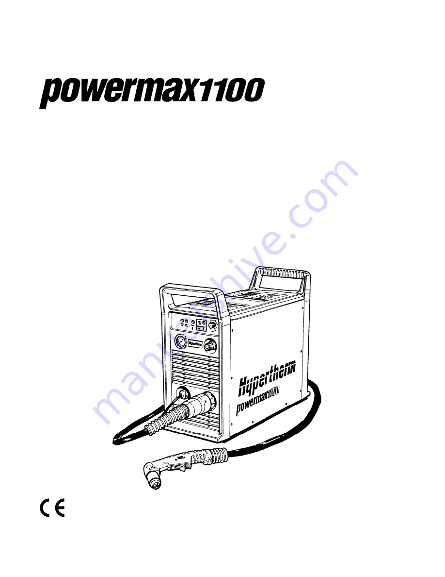
background image

Plasma Arc
Cutting System

Operator Manual
802730 Revision 1

®

EN50199
EN50192

Summary of Contents for Powermax 1100

Page 1: ...Plasma Arc Cutting System Operator Manual 802730 Revision 1 EN50199 EN50192 ...

Page 2: ...00 Revision 1 July 1999 Copyright 1999 Hypertherm Inc All Rights Reserved Hypertherm HyDefinition HT HyLife LongLife MAX PAC and Powermax are trademarks of Hypertherm Inc and may be registered in the United States and or other countries Hypertherm Inc Hanover NH http www hypertherm com email info hypertherm com ...

Page 3: ...9 6181 58 2100 Fax 49 6181 58 2134 European Technical Support Organization ETSO Technologiepark Hanau Rodenbacher Chaussee 6 D 63457 Hanau Wolfgang Germany Tel 49 6181 58 2100 Fax 49 6181 58 2134 Hypertherm Singapore Pte Ltd No 19 Kaki Bukit Road 2 K B Warehouse Complex Singapore 417847 Republic of Singapore Tel 65 841 2489 Fax 65 841 2490 Hypertherm U K 9 Berkeley Court Manor Park Runcorn Cheshir...

Page 4: ...he mains supply Consideration should be given to shielding the supply cable of permanently installed cutting equipment in metallic conduit or equivalent Shielding should be electrically continuous throughout its length The shielding should be connected to the cutting mains supply so that good electrical contact is maintained between the conduit and the cutting power source enclosure Maintenance of...

Page 5: ...ty with HYPERTHERM s specifications and in cases of designs processes formulae or combinations not developed or purported to be developed by HYPER THERM HYPERTHERM agrees to indemnify protect and hold harmless Distributors and their custom ers against any and all liability or claims in any manner imposed upon or accruing against Distributors and their customers because of the use in or about the c...

Page 6: ...ronic Health Support Equipment 1 4 SECTION 1A SÉCURITÉ 1a 1 Au sujet des Notes Attention et avertissement 1a 1 Consignes de sécurité 1a 2 Protection des yeux 1a 2 Protection de la peau 1a 2 Prévention des vapeurs toxiques 1a 2 Prévention des incendies 1a 2 Prévention des chocs électriques 1a 2 Prévention des explosions 1a 3 Protection contre le bruit 1a 4 Mise à la masse et à la terre 1a 4 Rappels...

Page 7: ...and Clamp 3 9 Gas Supply Requirements 3 9 Gas Supply Connection 3 10 Torch Lead Connection 3 11 Machine Interface with PAC135M 3 12 SECTION 4 OPERATION 4 1 Controls and Indicators 4 2 Operating Instructions 4 3 Operating Tips 4 6 Cut Chart 80A Standard Consumables 4 12 Cut Chart 40A Consumables 4 13 Common Cutting Faults 4 14 SECTION 5 MAINTENANCE PARTS 5 1 Introduction 5 2 Routine Maintenance 5 2...

Page 8: ...dy workpiece or the water in a water table when operating the plasma system When using a water table be sure that it is correctly connected to earth ground Operating the plasma system completes an electrical circuit between the torch and the workpiece and anything touching the workpiece The workpiece is part of the electrical circuit WARNING Instant On Torches Instant on torches produce a plasma a...

Page 9: ... an air supplied helmet 5 98 Fire Prevention Make fire extinguishers available in the cutting area Remove all combustible materials from the immediate cutting area to a distance of at least 35 feet 10 m Quench freshly cut metal or allow metal to cool before handling it or bringing it into contact with combustible materials Never use a plasma system to cut containers with potentially flammable mate...

Page 10: ...Examine hoses at regular intervals for leaks wear loose connections or other hazard Replace hose that is damaged in any way Electric Shock Prevention continued Before changing the torch parts disconnect the main power or unplug the power supply After changing torch parts and replacing the retaining cap plug in the power supply again Never bypass or shortcut the safety interlocks Before removing a ...

Page 11: ...d and the work cable Route torch leads as close as possible to work cable Do not wrap the torch lead or work cable around your body Stay as far away from the power supply as possible Hoses continued Keep hose lengths to a minimum to prevent damage reduce pressure drop and to prevent possible flow restrictions Prevent kinking by laying out hoses as straight as possible between termination points Co...

Page 12: ...s suivies correctement Prévention des incendies Avant de commencer s assurer que la zone de coupage ne présente aucun danger Conserver un extincteur à proximité Éloigner toute matière inflammable à une distance d au moins 10 m du poste de coupage Tremper le métal chaud ou le laisser refroidir avant de le manipuler ou avant de le mettre en contact avec des matériaux combustibles Ne jamais couper de...

Page 13: ...et remplacer les câbles de la torche qui sont usés ou endommagés Ne pas saisir la pièce à couper ni les chutes lors du coupage Laisser la pièce à couper en place ou sur la table de travail le câble de retour connecté lors du coupage Avant de vérifier de nettoyer ou de remplacer les pièces de la torche couper l alimentation ou débrancher la prise de courant Ne jamais contourner ou court circuiter l...

Page 14: ...er le câble de retour à la partie de la pièce qui doit se détacher Table de travail Raccorder la table de travail à la terre conformément aux codes de sécurité locaux ou nationaux appropriés MISE À LA MASSE ET À LA TERRE Alimentation S assurer que le fil de terre du cordon d alimentation est connecté à la terre dans le coffret du sectionneur S il est nécessaire de brancher le cordon d alimentation...

Page 15: ...à tout prix le contact électrique entre l arc plasma et une bouteille Ne jamais exposer des bouteilles à une chaleur excessive aux étincelles aux scories ou aux flammes nues Ne jamais utiliser des marteaux des clés ou d autres outils pour débloquer le robinet des bouteilles Une exposition prolongée au bruit du coupage ou du gougeage peut provoquer des problèmes auditifs Utiliser un casque de prote...

Page 16: ...tor Manual In this section Introduction 2 2 Specifications 2 3 Power Supply 2 3 PAC135 80A Torches 2 4 PAC135T Hand Torch Assembly 2 5 PAC135M Machine Torch Assembly 2 5 S Mark 2 5 IEC Symbols Used 2 6 Section 2 SPECIFICATIONS ...

Page 17: ...performance Cylinder air or shop air can be used as long as it is clean dry and oil free When properly set and maintained the pressure regulator and gas filter on the power supply ensure that the correct pressure and flow rate is supplied to the system at the proper quantity and quality The Powermax1100 can also cut with nitrogen when extended electrode life is a priority This instruction manual p...

Page 18: ...400V 48A 1φ 50 60 Hz 200V 56A 230V 49A 400V 28A 3φ 50 60 Hz 230V 33A 400V 19A CE 3φ 50 60 Hz 600V 20A 3φ 60 Hz Gas Type Air or Nitrogen Gas Quality Air Clean dry oil free Gas Quality Nitrogen 99 995 pure Gas Inlet Pressure 90 psi 6 2 bar Gas Flow 400 scfh 6 7 scfm at 90 psi 189 l min at 6 2 bar supplied to power supply pressure regulator Power Supply pressure regulator setting 65 psi 4 5 bar flowi...

Page 19: ...A Cutting Capacity PAC135M 1 2 12 mm 50 duty cycle Recommended 80A Cutting Capacity PAC135M 3 8 9 5 mm 100 duty cycle Maximum current at 50 duty cycle 80 amps Gas Flow 400 scfh 6 7 scfm at 65 psi 189 l min at 4 5 bar Gouging Capability metal removal rate 6 6 pounds 3 0 kg hr Weight PAC135T 9 3 pounds 4 2 kg with 25 ft 7 6 m lead 17 8 pounds 8 1 kg with 50 ft 15 m lead Weight PAC135M 9 6 pounds 4 4...

Page 20: ...s that the power supply and torch are suitable for use in environments with increased hazard of electrical shock The hand torches must have shielded consumable parts to maintain S mark compliance Figure 2 3 PAC135T Torch with Dimensions PAC135T Hand Torch Assembly 4 8 122 mm 3 5 89 mm 1 2 30 mm 1 9 48 mm 9 1 231 mm 1 2 30 mm 1 8 45 mm 55 3 3 83 mm 14 356 mm 10 8 274 mm 1 4 35 mm ...

Page 21: ... power connection The terminal for the external protective earth conductor An inverter based power source Anode work clamp Temperature switch Pressure switch Plasma torch in the TEST position cooling and cutting gas exiting nozzle Power is on Power is off Volt amp curve drooping characteristic IEC SYMBOLS USED ...

Page 22: ...wer Configurations 3 7 Single Phase 3 7 Three Phase 3 7 Power Cord Plugs 3 8 Power Requirements 3 8 Line Voltage Disconnect Box 3 8 Grounding Requirements 3 8 Work Cable and Clamp 3 9 Gas Supply Requirements 3 9 Air Supply Quality 3 9 Additional Air Filtration 3 10 Nitrogen Supply Quality 3 10 Gas Supply Connection 3 10 Torch Lead Connection 3 11 PAC135M ON OFF Pendant Connection 3 11 PAC135M Torc...

Page 23: ...this manual CLAIMS Claims for damage during shipment If your unit was damaged during shipment you must file a claim with the carrier Hypertherm will furnish you with a copy of the bill of lading upon request If you need additional assistance call Customer Service at 1 800 643 0030 in the U S and Canada or your authorized Hypertherm distributor Claims for defective or missing merchandise All units ...

Page 24: ... heed this warning could result in personal injury and damage to the power supply 1 Use a hoisting strap rated for a minimum hoisting weight of 400 pounds 182 kg Approved hoistingstrapshaveattachedlabelswithratings 2 Ensurethepowersupplycoverisinplacepriortohoisting 3 Route the strap between the two handles as shown in Fig 3 1 4 Bring the strap ends together over the center of the power supply and...

Page 25: ...the 600V transformer option kit configure the Powermax1100 for 480V WARNING SHOCK HAZARD Always turn off the power unplug the cord and wait 5 minutes before removing any power supply cover If the power supply is directly connected to a line disconnect switch place switch in the OFF position In the U S use a lock out tag out procedure until the service or maintenance work is complete In other count...

Page 26: ...ping for 208 240 480V and 200 230 400V Power Supplies POWER CORDS 208 240 480V 200 230 400V and 600V POWER SUPPLIES The 208 240 480V and 200 230 400V power supplies are shipped without a power cord Use the tables below to choose the proper wire size for the appropriate length cord In the U S use a 3 conductor SO type cord for single phase and a 4 conductor SO type cord for three phase power suppli...

Page 27: ...es 5 140 mm 7 5 178 mm Ground L1 L2 L3 Wind the ground wire 8 turns around the toroid 10 CHANGING THE STRAIN RELIEF SLEEVE Depending on the diameter of the power cord you choose the rear panel strain relief sleeve may need to be changed Alternate sleeves are located on the floor of the power supply behind the rear panel 1 Remove strain relief cap 2 Remove strain relief sleeve 3 Install new strain ...

Page 28: ... in this section Follow applicable local or national wire color conventions See also EMC Compatibility and Mains Supply on page i for further CE compliance recommendations Single Phase Remove the rear panel Fig 3 2 and connect the power cable to contactor as shown in Fig 3 9 Connect the ground wire to the stud marked Black White Green Figure 3 9 Single Phase Power Brown Conductor Color Line U Blac...

Page 29: ...ps 110 amp 240 VAC 1 80 amps 110 amp 400 VAC 1 48 amps 70 amp 480 VAC 1 40 amps 60 amp 200 VAC 3 56 amps 80 amp 208 VAC 3 53 amps 70 amp 230 VAC 3 49 amps 70 amp 230 VAC CE 3 33 amps 40 amp 240 VAC 3 46 amps 60 amp 400 VAC 3 28 amps 35 amp 400 VAC CE 3 19 amps 30 amp 480 VAC 3 23 amps 30 amp 600 VAC 3 20 amps 30 amp GROUNDING REQUIREMENTS To ensure personal safety proper operation and to reduce el...

Page 30: ... gas cylinders or liquid containers A high pressure regulator on either type of supply must be used and must be capable of delivering the following 400 scfh 6 7 scfm 189 l min at a pressure of 90 psi 6 2 bar to the filter on the power supply The filter location is shown in Fig 3 13 WARNING Do not allow the gas inlet pressure to the filter on the power supply to exceed 120 psi 8 2 bar The plastic f...

Page 31: ...cylinders or liquid containers GAS SUPPLY CONNECTION Use a 3 8 inch 9 5 mm ID inert gas hose to connect the gas supply air or nitrogen to the power supply filter To connect the hose install a 1 4 NPT nipple to the filter block as shown in Fig 3 13 Apply liquid pipe sealant to the threads to ensure a leak free installation A nipple and adapters are included in the consumable parts kit CAUTION Never...

Page 32: ...yplugwiththeconnectorreceptaclekeyslotonthepigtail andpushinuntilthepinsseat 2 Turntheconnectorsecuringringtotherighttotighten PAC135M Torch ON OFF Switch Connection Data The PAC135M torch lead is supplied with a pigtail so that the on off pendant may be used If you want to use a different on off switch configuration note that the wiring configuration to the 3 socket female receptacle on the pigta...

Page 33: ...torontherearpanelandconnectthemachine interfacecabletothecuttingmachine WARNING Do not connect the cutting machine interface START signal if using an ON OFF pendant Signal Type Notes Rear panel sockets Cable wires START start plasma Input Normally open 24 VAC open circuit voltage at START terminals Requires dry contact closure to activate 3 4 Green Black XFER start machine motion Output Normally o...

Page 34: ...Powermax1100 Figure 3 17 Machine Interface Board Connections for Arc Voltage Figure 3 16 Location of Arc Voltage Cable Strain Relief Strain Relief arc voltage cable 4 Routethecabletothemachineinterfaceboardlocatedonthetopofthepowersupplynearthe Powermax1100controlboard ConnectthearcvoltagecableasshowninFig 3 17 Tightenthe strainrelief START XFER ARC VOLTAGE J1 1 6 8 Signal Type Notes J1 6 J1 8 WAR...

Page 35: ...s 4 2 Operating Instructions 4 3 Pilot Arc Controller Optional 4 4 PAC135T Safety Trigger Operation 4 5 Operating Tips 4 6 Changing Consumable Parts 4 6 Cutting 4 8 Piercing 4 10 Gouging 4 11 Cut Chart 80A Standard Consumables 4 12 Cut Chart 40A Consumables 4 13 Common Cutting Faults 4 14 ...

Page 36: ...Green GAS PRESSURE LED When illuminated indicates that the gas pressure is within operating limits GAS TEST Switch When pushed in allows the operator to adjust the pressure setting AMPS Output Adjustment Knob Adjusts output current between 30 and 80 amps Pressure Regulator Regulates input gas pressure to the power supply Pressure Gauge Indicates gas pressure at the power supply ON I OFF 0 Power Sw...

Page 37: ...emain extinguished 4 Adjust the gas pressure REGULATOR to 65 psi 4 5 bar Pull the REGULATOR CAP out Push the GAS TEST switch in Turn the REGULATOR CAP while still pushing in the GAS TEST switch After adjusting to 65 psi 4 5 bar release the GAS TEST switch Push the REGULATOR CAP back in Note If using 50 ft 15 2 m torch leads adjust the pressure to 70 psi 4 8 bar 5 Adjust the AMPS knob to the desire...

Page 38: ...workpiece See Operating Tips and Cut Charts later in this section 9 When the cut is finished release the torch switch to extinguish the arc The arc will also extin guish when transfer to the workpiece is no longer sensed Pilot Arc Controller Optional In power supplies with the pilot arc controller option the torch will return to a pilot arc after finishing a cut if the torch switch remains pressed...

Page 39: ...ired Start pushing the safety forward Do not pull back on the trigger now wait until the safety reaches the Safety Off position as shown in step 3 1 2 Safety Off position In this position the trigger can be pulled back so that the torch can be fired 3 Release the safety to return to the Safety On position as shown in step 1 4 Figure 4 4 PAC135T Torch Safety Trigger Operation ...

Page 40: ...when the electrode is removed 6 Inspect the electrode If the center of the electrode has a pit more than 1 16 inch 1 6 mm deep replace it 7 Inspect the swirl ring It should be clean and the holes along the side should not be plugged If the swirl ring is damaged replace it 8 Inspect the O ring on the torch It should be lubricated and undamaged If it is dry lubricate it with a thin film of the lubri...

Page 41: ...iption of Consumables Shielded 80A For cutting above 40A Shielded nozzle allows the torch tip to be dragged directly on the workpiece Shielded 40A For optimal cutting on thinner materials at or below 40A Extended For increased visibility and access for special applications The nozzle is not shielded Maintain a standoff distance from the workpiece of approximately 1 8 3 mm when cutting above 40A to...

Page 42: ...oving the torch too fast or you do not have sufficient power to fully penetrate the workpiece Hold the torch lightly on the metal if using shielded consumables or just above the metal Holding the torch firmly to the workpiece causes the shield to stick and makes smooth cutting difficult The arc transfers to the workpiece once the torch is within 1 8 inch 3 mm of the workpiece Pulling the torch thr...

Page 43: ...OPERATION 4 9 Operator Manual Figure 4 8 Dragging the Torch Figure 4 7 Cutting a Circle ...

Page 44: ... angle to the workpiece away from yourself pull back on the trigger and slowly rotate the torch to an upright position This is particularly important when cutting thicker material Make sure that the torch is pointed away from you and the people near you to avoid any danger from sparks and hot metal When the pierce is complete bring the torch head to a perpendicular position and proceed with the cu...

Page 45: ...se serious burns if the skin is not covered Install the gouging nozzle and shield the same as a standard cutting nozzle and shield See Changing Consumable Parts earlier in this section Adjust the air pressure to 60 65 psi 4 1 4 5 bar with air flowing from the torch Note that this is lower than the cutting pressure Tilt the torch approximately 45 from the surface to be gouged and push the torch in ...

Page 46: ... 5 Stainless Steel 80 122 53 1345 1 00 1 2 12 7 Stainless Steel 80 123 32 810 1 25 5 8 15 9 Stainless Steel 80 123 25 635 1 75 3 4 19 0 Stainless Steel 80 126 18 460 n a 1 25 4 Stainless Steel 80 133 10 255 n a 1 8 3 2 Aluminum 80 119 340 8640 0 1 4 6 4 Aluminum 80 120 140 3560 0 25 3 8 9 5 Aluminum 80 122 90 2285 0 50 1 2 12 7 Aluminum 80 129 60 1525 1 00 3 4 19 0 Aluminum 80 131 31 790 n a Recom...

Page 47: ...steel 40 116 70 1780 1 00 1 4 6 4 Mild steel 40 119 42 1070 1 25 3 8 9 5 Mild steel 40 126 19 480 n a 1 2 12 7 Mild steel 40 131 14 355 n a 26 ga 0 5 Stainless steel 30 116 520 13200 0 22 ga 0 8 Stainless steel 30 116 260 6600 0 20 ga 0 9 Stainless steel 30 117 170 4320 0 18 ga 1 2 Stainless steel 40 116 310 7870 0 16 ga 1 5 Stainless steel 40 117 200 5080 0 14 ga 1 9 Stainless steel 40 115 170 43...

Page 48: ...cap may become hot To cool it push in and hold the GAS TEST switch until the cap cools down The duty cycle or the amount of time the pilot or plasma arc can remain on in minutes within a 10 minute period is affected by many factors When the current is set at 80 amps the Powermax1100 has a 50 duty cycle at a temperature of 104 F 40 C At these conditions the plasma arc can remain on 5 minutes out of...

Page 49: ...placement of the Cooling Air Filter 5 3 BasicTroubleshooting 5 4 Technical Questions 5 7 Parts 5 8 PAC135 Consumable Parts 5 8 Consumable Parts Kits 5 9 PAC135T Torch Assembly 5 10 PAC135M Torch Assembly 5 11 Powermax1100 Field Upgrade Kits and Optional Parts 5 12 Power Supplies 208 240 480V 5 12 Power Supplies 200 230 400V 5 12 Power Supplies 230 400V CE 5 12 In this section ...

Page 50: ...s up in the bowl of the filter drain the bowl and clean the filter element 1 Shut off the gas supply and disconnect the gas supply hose from the filter assembly before proceeding 2 Remove the cap at the bottom of the filter bowl and turn the knurled drain valve to the right to release water from the bowl 3 Unscrew the filter bowl 4 Unscrew the filter element 5 Clean the filter element with alcohol...

Page 51: ...that secure the power supply cover to the chassis 3 Remove the cover and remove the cooling air filter from the clips by sliding the filter to the left and then up 4 Clean the air filter with either soap and water or with low pressure compressed air 5 Replace the dry filter in the power unit with the wire mesh facing the fan 6 Replace and refasten the power supply cover s screws WARNING SHOCK HAZA...

Page 52: ...ssure to 90 psi 6 2 bar Verify that there are no leaks in the gas supply line 3 1 Power supply voltage links are incorrect See voltage configuration settings in Section 3 3 2 Line voltage is too low The following table represents the operating range of the Powermax1100 power supplies Have an electrical technician check incoming power BASIC TROUBLESHOOTING ON OFF Power Switch POWER ON LINE VOLTAGE ...

Page 53: ...ks are incorrect See voltage configuration settings in Section 3 5 2 Line voltage is too high See the table above 6 1 The power supply has exceeded the capacity of the fuse Check the fuse for proper amperage rating See Power Requirements in Section 3 Check power cable for a short circuit or loose connection 7 1 One of the internal thermostat switches has opened due to overheating Leave power suppl...

Page 54: ...maximum distance to the workpiece and start the torch again 9 1 There are faulty consumable parts Inspect and change the consumable parts if necessary See Operating Tips in Section 4 9 2 The gas pressure is incorrect See Operating Instructions in Section 4 to adjust the gas pressure if necessary 9 3 The gas filter at the rear of the supply contains excessive moisture Drain the filter bowl and clea...

Page 55: ...ed Hypertherm repair facility 2 Call the nearest Hypertherm office listed in the front of this manual 3 See the Powermax1100 service manual for wiring diagrams higher level troubleshooting and more parts list information 11 The torch cuts poorly Problem Cause Solution 11 1 Power supply voltage links are incorrect See voltage configuration settings in Section 3 11 2 Torch consumables are worn See O...

Page 56: ...nsumable parts Retaining Cap 120520 40A Retaining Cap 120483 80A Electrode 120473 Swirl Ring 120474 Hand Shield 120475 Nozzle 120515 40A Shield 120510 Nozzle 120509 Nozzle 120476 80A Gouging Shielded 80A 40A Extended Deflector 120519 Nozzle 120518 Electrode 120517 Retaining Cap 120483 Retaining Cap 120483 Machine Shield 120516 Electrode 120473 ...

Page 57: ...x Consumable Parts Part Number Description 120473 Electrode PAC135 120476 Nozzle PAC135 80A 120509 Nozzle PAC135 Gouging 120475 Shield PAC135 Hand 120510 Shield PAC135 Gouging 026020 O Ring 864 X 070 027055 Lubricant Silicone 1 4 Oz Tube 027526 Electrode Wrench PAC135 015145 Adapter 1 4NPT X G 1 4 Hose 001285 Box Consumable Parts Part Number Description 120473 Electrode PAC135 120516 Shield PAC135...

Page 58: ... Swirl Ring PAC135 1 120475 Shield PAC135 80A 1 120476 Nozzle PAC135 80A Shield 1 120483 Retaining Cap PAC135 1 5 120477 Torch Main Body PAC135T 1 6 026020 O Ring Silicon 864 X 070 1 7 129559 Torch Lead 25 ft 7 6 m 1 7 129560 Torch Lead 50 ft 15 2 m 1 8 005247 Push Button Switch Lo Profile 1 9 128122 Plug Assembly PAC135T Torch Quick Disconnect 1 10 074069 Splice 22 18 Butt 2 11 046056 Tubing 5 8 ...

Page 59: ... 2 m 1 3 128122 Plug Assembly PAC135 Torch Quick Disconnect 1 4 008268 Plug 3 Socket Female 1 5 108034 Receptacle Housing 2 Position 26 22AWG 1 120473 Electrode 1 120474 Ring Swirl 1 120516 Shield PAC135M Machine Torch 1 120476 Nozzle PAC135 80A Shield 1 120483 Cap Retaining 1 6 120508 Torch Main Body PAC135M 1 7 026020 O Ring Silicon 864 X 070 1 8 108035 Pin Housing 2 Position 26 22AWG 1 9 108040...

Page 60: ...em configurations and with machine interface kits 109068 Toroid for power cord ground Powermax1100 CE power supplies only 002282 Strain Relief Sleeve 0 875 002283 Strain Relief Sleeve 0 750 002286 Strain Relief Sleeve 0 625 Shipped in CE power supply rear panels Note Field upgrade kits must be installed by qualified service personnel POWER SUPPLIES 208 240 480V 1φ 3φ 50 60 HZ Part For With Pilot A...

Page 61: ...inable from the National Fire Protection Association 470 Atlantic Avenue Boston MA 02210 9 NFPA Standard 70 1978 National Electrical Code obtainable from the National Fire Protection Association 470 Atlantic Avenue Boston MA 02210 10 NFPA Standard 51B Cutting and Welding Processes obtainable from the National Fire Protection Association 470 Atlantic Avenue Boston MA 02210 11 CGA Pamphlet P 1 Safe ...

Page 62: ...install an aeration manifold on the floor of the water table to replenish the oxygen content of the water Making an Aeration Manifold Figure b 1 Make an Aeration Manifold with two inch 50 mm PVC tubing with one inch 25 mm Distribution Lines connected to it Drill 1 8 inch 3 mm holes every six inches 150 mm in the distribution lines Cap the ends of the distribution lines and install the lines so tha...

Reviews: