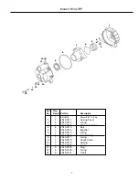
Series 1542A-SP, 1543A-SP & 1543A-TSP
Gas Engine-Driven, Self-Priming
Centrifugal Pump
General Safety Information
Description
Installation, Operation, Repair and Parts Manual
Form L-1515
(12/07)
Hypro Self-Priming Centrifugal Pumps handle big, high-
capacity, liquid transfer jobs with ease. Use them for
transferring water, liquid fertilizers, and other chemicals
compatible with pump materials. Make short work of other
farm jobs: filling nurse tanks, watering seedbeds, and
transferring liquids. This self-priming model makes it ideal
for de-watering applications.
1542A-SP
Close-Coupled, Gas Engine-Driven
Self-Priming Centrifugal Pump
Max Flow Rate: ............................147 GPM
Max. Pressure: ................................50 PSI
Max. Total Head ..............................115 FT.
Max. Suction Lift: ..............................28 FT.
Ports: ........................................2" BSP Inlet
2" BSP Outlet
Engine ............................PowerPro
™
5.5 HP
1543A-SP
Close-Coupled, Gas Engine-Driven
Self-Priming Centrifugal Pump
Max Flow Rate: ............................259 GPM
Max. Pressure: ................................43 PSI
Max. Total Head ..............................100 FT.
Max. Suction Lift: ..............................28 FT.
Ports: ........................................3" BSP Inlet
3" BSP Outlet
Engine ............................PowerPro
™
6.5 HP
1543A-TSP
Close-Coupled, Gas Engine-Driven
Self-Priming Centrifugal Trash Pump
Max Flow Rate: ..........................272 GPM
Max. Pressure: ..............................50 PSI,
Max. Total Head ..............................115 FT.
Max Suction Lift: ..............................28 FT.
Ports:........................................3" BSP Inlet
3" BSP Outlet
Engine............................PowerPro
™
6.5 HP
Max dia. ........................................1” solids
WARNING: Do not pump flammable or explosive fluids
such as gasoline, fuel oil, kerosene, etc. Do not use in
explosive atmospheres. The pump should be used only
with liquids that are compatible with the pump
component materials. Failure to follow this warning
can result in personal injury and/or property damage
and will void the product warranty.
1. DO NOT EXCEED recommended speed, pressure and
temperature (140˚ F) for pump and equipment being
used.
2. BEFORE SERVICING, drain all liquids from the system
and flush. Remove the spark plug wire from the spark
plug before servicing the pump or engine.
3. Secure the discharge lines before starting the pump.
An unsecured line may whip, causing personal injury
and/or property damage.
4. Check hose for weak or worn condition before each
use. Make certain that all connections are tight and
secure.
5. Periodically inspect the pump and the system
components. Perform routine maintenance as required
(see Maintenance section).
6. Protect pump from freezing conditions by draining
liquid and pumping a permanent-type automobile
antifreeze containing a rust inhibitor through the
system, coating the pump interior. A 50% mixture with
water is recommended.
7. Do not operate a gasoline engine in an enclosed area.
Be sure the area is well ventilated.
WARNING: Gasoline is a highly combustible fuel. The
improper use, handling, or storage of gasoline can be
dangerous. Never touch or fill a hot engine.
8. Use only pipe, hose and fittings rated for the maximum
psi rating of the pump.
9. Do not use these pumps for pumping water or other
liquids for human or animal consumption.


