
The standard configuration of this product is comprised of the following parts.
If you find any fault with the product you have received, or any missing parts, contact us or our distributor.
1. Parts
(The option is excluded)
No.
Part Name
Model
Q'ty
Reference
1
Main Body (with 5m
standard cable)
Refer to “How to Read model Nameplate”,
“How to read model Number”
1
Standard cable is fixed on
main body.
Accessories
2
Position controller /
ELECYLINDER cable
CB-TB1-C002 1
When model C and SC selected
3 Program
controller
cable
CB-TB1-X002 1
When model S and SC selected
4 Conversion
Cable
CB-SEL-SJS002 1
When model S and SC selected
5 Touch
Pen
TCH-TB02 1
Provided with the main body
4.5 x 102mm
6 Safety
Guide
M0194 1
7
First Step Guide
ME0358 1
This
guide
8
Instruction Manual (DVD) 1
2. Instruction manuals related to this product, which are contained in the DVD.
No.
Name
Manual No.
1
Touch Panel Teaching TB-02 Applicable for Position Controller / ELECYLINDER
Instruction Manual
ME0355
2
Touch Panel Teaching TB-02 Applicable for Program Controller Instruction Manual
ME0356
3
Actuator with Integrated ERC2 Controller Instruction Manual <PIO type>
ME0158
4
Actuator with Integrated ERC2 Controller Instruction Manual <SIO type>
ME0159
5
Actuator with Integrated ERC3 Controller Instruction Manual
ME0297
6
PCP6S Field Bus Communication Instruction Manual
ME0349
7 ACON-CA/DCON-CA
Controller
Instruction
Manual
ME0326
8
ACON-CB/CGB, DCON-CB/CGB Controller Instruction Manual
ME0343
9
ACON-CYB/PLB/POB, DCON- CYB/PLB/POB Controller Instruction Manual
ME0354
10
PCON-CA/CFA Controller Instruction Manual
ME0289
11
PCON-CB/CGB/CFB/CGFB Controller Instruction Manual
ME0342
12
PCON-CYB/PLB/POB Controller Instruction Manual
ME0353
13
SCON-CA/CAL/CGAL Controller Instruction Manual
ME0243
14
SCON-CB/CGB Controller Instruction Manual
ME0340
15 ROBONET
Instruction
Manual
ME0208
16
ASEP/PSEP/DSEP Controller Instruction Manual
ME0267
17
PMEC/AMEC Controller Instruction Manual
ME0245
18
MSEP-C/LC Controller Instruction Manual
ME0299
19
MCON-C/CG/LC/LCG Controller Instruction Manual
ME0341
20
MSCON Controller Instruction Manual
ME0306
21
RCON System Instruction Manual
ME0384
22
RSEL System Instruction Manual
ME0392
23
REC System Instruction Manual
ME0394
24
ASEL Controller Instruction Manual
ME0165
25
PSEL Controller Instruction Manual
ME0172
26
SSEL Controller Instruction Manual
ME0157
27
MSEL-PC/PG/PCX/PGX Controller Instruction Manual
ME0336
28
XSEL-P/Q/PCT/QCT Controller Instruction Manual
ME0148
29
XSEL-PX/QX Controller Instruction Manual
ME0152
30
XSEL-R/S/RX/SX/RXD/SXD Controller Instruction Manual
ME0313
31
XSEL-RA/SA/RAX/SAX/RAXD/SAXD Controller Instruction Manual
ME0359
32
Tabletop Robot TT Controller Instruction Manual
ME0149
33
Tabletop Robot TTA Controller Instruction Manual
ME0320
34
ELECYLINDER Instruction Manual
ME3778/3779/3793/3794
ME3798/3799/3800/3801
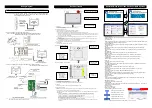
3. How to Read Model Nameplate
4. How to Read Model Number
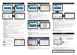
Supported Models
Supported Models of Position Controller
Supported Models of Program Controller
Note 1 Only ERC2 models with 4904 or higher stamped on the Serial No. sticker can be connected.
However, touch-panel teaching pendants can be connected to ERC2 controllers of SE type via a SIO converter
regardless of their version.
For details, refer to the instruction manual.
Note 2 MCON-C/CG applicable for SSCNETIII/H, MECHATROLINK-III and EtherCAT Motion in V1.20 and later
Supported Models of ELECYLINDER
ELECYLINDER model
Note 1
Supported from version
Standard type
Digital speed
controller type
EC-S6, EC-S7, EC-R6, EC-R7
V1.60
V2.60
EC-S6
□
H, EC-S7
□
H, EC-RR6, EC-RR7, EC-R6
□
W, EC-R7
□
W,
EC-RP4, EC-GS4, EC-GD4, EC-TC4, EC-TW4
V2.00
EC-RR6
□
H, EC-RR7
□
H V2.10
EC-S6
□
AH, EC-S7
□
AH, EC-RR6
□
AH, EC-RR7
□
AH V2.30
EC-S3, EC-S4, EC-S6
□
R, EC-S7
□
R, EC-S6
□
AHR, EC-S7
□
AHR,
EC-RR3, EC-RR4, EC-RR6
□
R, EC-RR7
□
R, EC-RR6
□
AHR, EC-RR7
□
AHR
V2.40
EC-RR6
□
W, EC-RR7
□
W V2.50
EC-B6, EC-B7
V2.60
EC-S3
□
R, EC-S4
□
R, EC-RR3
□
R, EC-RR4
□
R,
EC-RTC9, EC-RTC12, EC-ST15
V2.70
EC-S13, EC-S13X, EC-S15, EC-S15X
V2.80
-
Make sure to use in a version that support is started or later. (Some functions may not be able to use in a version before
support.)
Note 1 For the digital speed controller type, the model code includes “D” in the type.
e.g. EC-S3
→
EC-DS3, EC-RR6
→
EC-DRR6
There are some models that have no digital speed controller type in the lineup.
Supported Models of Gateway Parameter Setting Tool
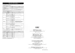
Confirming the Specifications
1. Basic Specification
Item
Basic Specification
Position controller / ELECYLINDER
connection
Program controller connection
Power Supply Voltage Range
24V DC±10% (Supplied by controller)
Power Supply Current
150mA or less
Power Consumption
3.6W or less
Insulation Resistance
500V DC /10M
or more between GND and FG
Grounding -
Functional ground (by shield in the
connection cable with controller)
LC/Backlight
7-inch color TFT WVGA (800×480), 65536 colors (16 bits)/White LED backlight
Backlight Life
15000 hours
Touch Panel
4-wire resistive type
Touch Panel Life
1 million touches
External Memory
SD/SDHC memory card interface installed (1G to 32G) (Toshiba-made
recommended)
Data Storage
Applicable to have data saved to and read from external Secure Digital card
(Position data, parameter, alarm list)
Data Backup Battery Life
5 years
Touch Tone
Turned ON/OFF. Volume is adjustable by 3 stages (High/Medium/Low).
Display Adjustment
Brightness adjustable for contrast and backlight
Clock Setting
Clock setting available with real time clock (Backup held with CR2032 button battery)
Communication Standard
Based on RS485
Based on RS232
Communication Speed
115,200bps
9,600bps/19,200bps/38,400bps
/57,600bps/115,200bps/230,400bps
Cable Length
Standard 5m/Max. 10m
Wall-mounting Hook
Hook available to use with M8 hex socket head cap screw
Time from Power OFF to ON
2 sec or more
Air-cooling System
Natural air-cooling
Languages Japanese/English/Chinese
Mass
TB-02: Approx. 470g (Main body) + Approx. 330g (cable 5m)
TB-02D: Approx. 600g (Main body) + Approx. 330g (cable 5m)
Secure Digital memory card is a registered trademark for SD-3C, LLC and SDA.
2. Environmental Specifications
Item
Environmental Specifications
Ambient Operating Temperature
0 to 40°C
Ambient Operating Humidity
85%RH or less (non-condensing)
Ambient Storage Temperature
-20 to 70°C
Ambient Storage Humidity
85%RH or less (non-condensing)
Vibration Endurance
Vibration 10 - 57Hz/Amplitude: 0.035mm (continuous), 0.075mm (intermittent)
Vibration 57 - 150Hz/Acceleration: 4.9m/s
2
(continuous), 9.8m/s
2
(continuous)
X/Y/Z direction Sweep time: 10 min. Sweep repetition: 10 times
Altitude
1000 meters or less above the sea level
Atmosphere
Environment without corrosive and combustible gas.
Avoid using the equipment where there is much dust and oil mist/
cutting fluid is sprinkled.
Pollution Level
Ⅱ
Protective Structure
IP20
Protective Class against
Electric Shock
Ⅲ
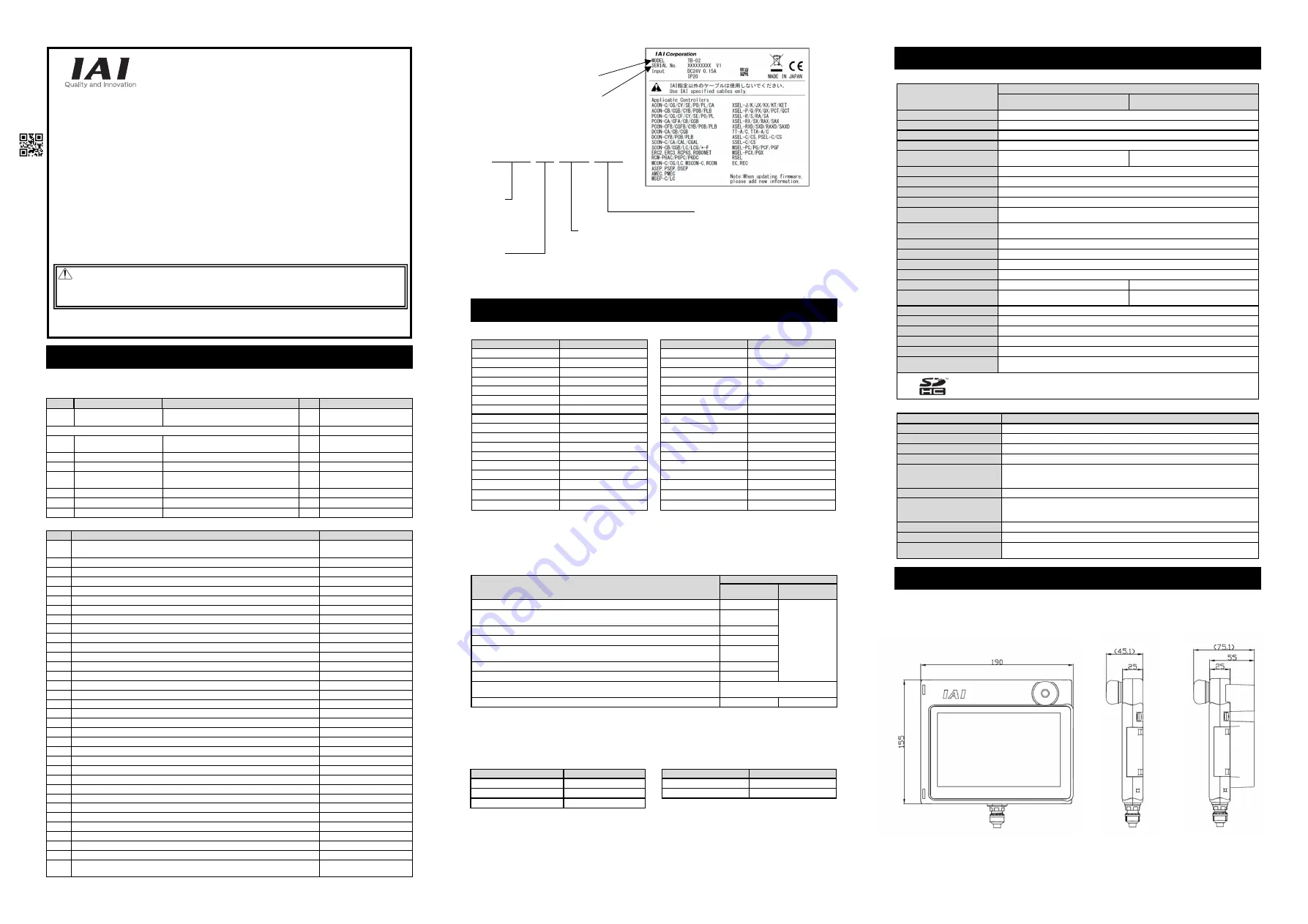
External Dimensions
Front Side
Touch Panel Teaching
Pendant TB-02
Applicable for Position Controller,
ELECYLINDER & Program Controller
First Step Guide
Eighth Edition
Thank you for purchasing our product.
Make sure to read the Safety Guide and detailed Instruction Manual (DVD) included with the product in addition to
this First Step Guide to ensure correct use.
This Instruction Manual is original.
Using or copying all or part of this Instruction Manual without permission is prohibited.
The company names, names of products and trademarks of each company shown in the sentences are registered
trademarks.
Product Check
Controller model
Supported from version
ASEL/PSEL/SSEL V1.00
TT V1.00
TTA V1.00
MSEL-PC/PG/PCX/PGX V1.00
MSEL-PCF/PGF V1.60
XSEL-J/K V1.00
XSEL-JX/KX V1.00
XSEL-KT/KET V1.00
XSEL-P/Q/PCT/QCT V1.00
XSEL-PX/QX V1.00
XSEL-R/S V1.00
XSEL-RX/SX V1.00
XSEL-RXD/SXD V1.00
XSEL-RA/SA V1.30
XSEL-RAX/SAX V1.30
XSEL-RAXD/SAXD V1.30
RSEL V2.70
Controller model
Supported from version
ERC2
(Note 1)
V1.00
ERC3 V1.00
ACON V1.00
DCON V1.00
PCON V1.00
SCON V1.00
SCON (Servo Press Type)
V1.40
MCON
(Note 2)
V1.00
MSCON V1.00
RCON V2.10
RCP6S V1.00
RCM-P6
□
C V1.50
RACON/RPCON V1.00
ASEP/DSEP/PSEP V1.00
MSEP V1.00
AMEC/PMEC V1.00
REC V2.70
Controller model
Supported from version
Controller model
Supported from version
MSEP-C V1.00
RCP6S Gateway
V1.00
MCON-C/CG V1.00
RCON V2.10
REC V2.70
T B - 0 2 - S C - S W R - E N G
<Model number>
TB-02 :
Standard
type
TB-02D : With deadman
switch type
(left side)
<Language option>
Not specified : Screens are displayed in Japanese.
(Display can be changed to other
language)
ENG
: Screens are displayed in English.
(Display can be changed to other
language)
CHI
: Screens are displayed in Chinese.
(Display can be changed to other
language)
<Cable Type>
SCN : With No Cable (Main body only)
C
: With Position Controller / ELECYLINDER Cable
S
: With Program Controller Cable and Conversion Cable
SC : With Program Controller Cable, Conversion Cable and Position Controller / ELECYLINDER Cable
Note : It is necessary to provide a special cable (CB-TB1-XJ005) for XSEL-J/JX controller.
Model number
Serial number
<Switch specification>
Not specified : Stop switch unit is gray.
SWR
: Stop switch unit is red.
Warning : Operation of this equipment requires detailed installation and operation instructions which are
provided on the DVD Manual included in the box this device was packaged in. It should be retained
with this device at all times.
A hardcopy of the Manual can be requested by contacting your nearest IAI Sales Office listed at
the back cover of the Instruction Manual or on the First Step Guide.
8A
Standard Specification
Deadman Switch Specification
Standard Specification
(without Deadman Switch)
Deadman Switch
Specification


