background image

BladeCenter T Type 8267

Hardware Maintenance Manual and Troubleshooting
Guide

Summary of Contents for BladeCenter T

Page 1: ...BladeCenter T Type 8267 Hardware Maintenance Manual and Troubleshooting Guide ...

Page 2: ......

Page 3: ...BladeCenter T Type 8267 Hardware Maintenance Manual and Troubleshooting Guide ...

Page 4: ...tal Notices and User Guide on the IBM Documentation CD and the Warranty Information document The most recent version of this document is available at http www ibm com supportportal First Edition September 2011 Copyright IBM Corporation 2011 US Government Users Restricted Rights Use duplication or disclosure restricted by GSA ADP Schedule Contract with IBM Corp ...

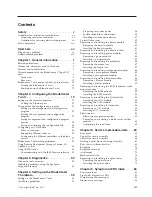
Page 5: ...es 35 Preparing for system power 36 System reliability considerations 36 Handling static sensitive devices 37 Preinstallation steps 39 Removing and installing the bezel assembly 40 Removing the bezel assembly 40 Installing the bezel assembly 41 Removing and installing the bezel air filter 41 Removing and installing power modules 43 Removing a power module 45 Installing a power module 45 Removing a...

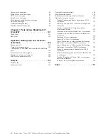
Page 6: ...tory statement 110 Electronic emission notices 110 Federal Communications Commission FCC statement 110 Industry Canada Class A emission compliance statement 110 Avis de conformité à la réglementation d Industrie Canada 110 Australia and New Zealand Class A statement 111 European Union EMC Directive conformance statement 111 Germany Class A statement 111 Japan VCCI Class A statement 112 Japan Elect...

Page 7: ...odukt Lees voordat u dit product installeert eerst de veiligheidsvoorschriften Ennen kuin asennat tämän tuotteen lue turvaohjeet kohdasta Safety Information Avant d installer ce produit lisez les consignes de sécurité Vor der Installation dieses Produkts die Sicherheitshinweise lesen Prima di installare questo prodotto leggere le Informazioni sulla Sicurezza Copyright IBM Corp 2011 v ...

Page 8: ...ressed in this section If you identify an unsafe condition you must determine how serious the hazard is and whether you must correct the problem before you work on the product Consider the following conditions and the safety hazards that they present v Electrical hazards especially primary power Primary voltage on the frame can cause serious or fatal electrical shock v Explosive hazards such as a ...

Page 9: ...Do not use this type of mat to protect yourself from electrical shock v Do not work alone under hazardous conditions or near equipment that has hazardous voltages v Locate the emergency power off EPO switch disconnecting switch or electrical outlet so that you can turn off the power quickly in the event of an electrical accident v Disconnect all power before you perform a mechanical inspection wor...

Page 10: ...labeled with a number This number is used to cross reference an English language caution or danger statement with translated versions of the caution or danger statement in the Safety Information document For example if a caution statement is labeled Statement 1 translations for that caution statement are in the Safety Information document under Statement 1 Be sure to read all caution and danger st...

Page 11: ...ct and disconnect cables as described in the following table when installing moving or opening covers on this product or attached devices To Connect To Disconnect 1 Turn everything OFF 2 First attach all cables to devices 3 Attach signal cables to connectors 4 Attach power cords to outlet 5 Turn device ON 1 Turn everything OFF 2 First remove power cords from outlet 3 Remove signal cables from conn...

Page 12: ...n those specified herein might result in hazardous radiation exposure DANGER Some laser products contain an embedded Class 3A or Class 3B laser diode Note the following Laser radiation when open Do not stare into the beam do not view directly with optical instruments and avoid direct exposure to the beam Class 1 Laser Product Laser Klasse 1 Laser Klass 1 Luokan 1 Laserlaite Appareil A Laser de Cla...

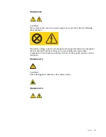
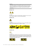
Page 13: ...voltage current and energy levels are present inside any component that has this label attached There are no serviceable parts inside these components If you suspect a problem with one of these parts contact a service technician Statement 12 CAUTION The following label indicates a hot surface nearby Statement 13 Safety xi ...

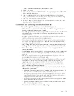
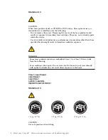
Page 14: ... installing the blade Statement 32 CAUTION To avoid personal injury before lifting the unit remove all the blades power supplies and removable modules to reduce the weight 8X 4X 4X 86 kg 190 lbs 39 kg 85 lbs Statement 33 CAUTION This device does not provide a power control button Removing power supply modules or turning off the server blades does not turn off the electrical current supplied to the...

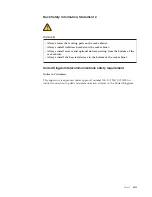
Page 15: ...ers and optional devices starting from the bottom of the rack cabinet v Always install the heaviest devices in the bottom of the rack cabinet United Kingdom telecommunications safety requirement Notice to Customers This apparatus is approved under approval number NS G 1234 J 100003 for indirect connection to public telecommunication systems in the United Kingdom Safety xiii ...

Page 16: ...xiv BladeCenter T Type 8267 Hardware Maintenance Manual and Troubleshooting Guide ...

Page 17: ...lade server is designed for ease of diagnosis of hardware and software problems v Light path diagnostics LEDs See Light path diagnostics LEDs on page 92 for information about light path diagnostics LEDs that are lit and actions that you should take v Event logs See Error symptoms on page 83 for information about notification events and diagnosis v Software or operating system error codes See the d...

Page 18: ... support fixcentral systemx groupView query productGroup ibm 2FSystemx To display a list of available updates for the blade server go to http www ibm com support fixcentral systemx groupView query productGroup ibm 2FBladeCenter When you click an update an information page is displayed including a list of the problems that the update fixes Review this list for your specific problem however even if ...

Page 19: ...toms Follow the troubleshooting procedure for the most obvious symptom If that procedure does not diagnose the problem use the procedure for another symptom if possible If the problem remains contact IBM or an approved warranty service provider for assistance with additional problem determination and possible hardware replacement To open an online service request go to http www ibm com support ele...

Page 20: ...xviii BladeCenter T Type 8267 Hardware Maintenance Manual and Troubleshooting Guide ...

Page 21: ...lade servers that support the KVM function keyboard video and mouse Performance ease of use reliability designed for NEBS Level 3 compliance and expansion capabilities were key considerations during the design of the BladeCenter T system These design features make it possible for you to customize the system hardware to meet your needs today while providing flexible expansion capabilities for the f...

Page 22: ...zel assembly if ordered with your system v Front of the BladeCenter T unit The labels on the top and the front of the bezel assembly of the BladeCenter T unit are shown in the following illustration CM M 1 CM M 2 ESD Information label Serial number label A set of user labels comes with each blade server When you install a blade server in the BladeCenter T unit write identifying information on a la...

Page 23: ... language in the Safety Information document v Installation and User s Guide The Installation and User s Guide contains general information about the chassis including how to install supported optional devices v BladeCenter T Rack Installation Instructions These documents contain instructions for installing the BladeCenter T unit in a 4 post and 2 post rack Note The BladeCenter T can also be insta...

Page 24: ...or problem situations v Attention These notices indicate possible damage to programs devices or data An attention notice is placed just before the instruction or situation in which damage could occur v Caution These statements indicate situations that can be potentially hazardous to you A caution statement is placed just before the description of a potentially hazardous procedure step or situation...

Page 25: ...firmware UEFI service processor Size 8 U v Height 349 25 mm 13 75 in or 8 U v Depth 508 mm 20 in from front of chassis to rear I O connector plane Maximum depth 600 mm 23 62 in including bezel handles and cable bend radius v Width 442 mm 17 4 in v Weight Fully configured with modules and blade servers Approx 89 4 kg 197 lb Shipping without blade servers Approx 52 6 kg 116 lb Security features v Lo...

Page 26: ...deCenter T unit port specifications see BladeCenter T unit power controls and indicators on page 15 2 For information about which types of I O modules can be installed in which I O module bays see I O modules on page 15 3 The operating system in the blade server must provide USB support for the blade server to recognize and use the keyboard mouse and DVD CD RW drive The BladeCenter T unit uses USB...

Page 27: ...le bay 1 Power module 3 Power module 1 Power module 4 Power module 2 Front panel Media tray ESD connector Management module bay 2 CMM 1 CMM 2 Blade server 1 Blade server 8 System service cards These cards contain system service instructions and a writable area for your use The cards are located in a slot just above the management module bays To access the service cards slide out the cards as shown...

Page 28: ...tem error LED critical major or minor on each of the BladeCenter T system status panels is also lit Management module IP reset button Do not press this button unless you intend to erase your configured IP addresses for the management module and lose connection with the remote management station the switch modules and the blade servers If you press this button you must reconfigure the management mo...

Page 29: ...T unit v Power When continuously lit this green LED indicates the presence of power in the BladeCenter T unit The LED turns off when the power source is interrupted Attention If the power LED is off it does not mean electrical power is not present in the BladeCenter T unit The LED might be burned out To remove all electrical power from the BladeCenter T unit you must disconnect all power cords fro...

Page 30: ...m fault A minor system fault is an error or event that has little impact to system operation An example is a correctable ECC error USB connectors There are two USB connectors on the front system status panel You can use these USB connectors to connect two USB peripheral devices without an external hub If more devices are required you can connect an external hub to any of the built in connectors Po...

Page 31: ... problem Possible causes v There is no power to the power module Actions Make sure that 1 The power is correctly connected to the unit 2 The power is connected to 110 v ac or 220 v ac 3 The power source functions properly v The power module has failed Action Replace the power module If the problem remains have the unit serviced Error LED will operate only if a redundant power supply is installed O...

Page 32: ... unit comes with four blowers that are in a 3 1 redundancy configuration All the cooling requirements are met if one blower fails All blowers contain a backflow device that prevents the system from drawing air into the exhaust port of a failed blower The management module in the BladeCenter T unit controls the blower speed and detects blower failures Blower Error LED Power LED Blower LEDs The LEDs...

Page 33: ...ladeCenter T unit for service or repair You can turn off the location LED through the web interface or a remote management console Alarm LEDs These LEDs provide alarm notifications for the BladeCenter T unit v CRT Critical alarm amber default or red When continuously lit this LED indicates the presence of a critical system fault The system comes with amber as the default See the documentation that...

Page 34: ...nit for the two local area network Ethernet connections as driven from each management module and the telco external alarms This module contains two RJ 45 connectors with LEDs and one DB60 serial connector 2 1 Ethernet link LED Ethernet activity LED Serial connector DB60 Remote management and console Ethernet Thumbscrews LAN module LEDs These LEDs provide status information about the LAN connectio...

Page 35: ...nnect directly to PC Connect through an Ethernet switch LAN module 192 168 70 125 192 168 70 135 192 168 70 155 Ethernet switch RJ 45 connector Standard Ethernet cable Standard Ethernet cables I O modules You can install a maximum of four I O modules at the rear of the system a maximum of four Gigabit Ethernet switches or a maximum of two Gigabit Ethernet switches and two Fibre Channel switches Th...

Page 36: ...led instructions AC in LED DC out LED Error LED AC power module Make sure that the LEDs on the power modules indicate that they are operating correctly Make sure that the input and output power LEDs on each power module are lit and the error LEDs are not lit 4 Before proceeding make sure that the LEDs on the blower modules indicate that they are operating correctly Make sure that the power LED on ...

Page 37: ... Guide for your blade server on the IBM Documentation CD that comes with the blade server for the location of the blade server LEDs Shutting down the BladeCenter T unit You can shut down the BladeCenter T unit by turning off the blade servers and disconnecting the BladeCenter T unit from the power source Complete the following steps to shut down the BladeCenter T unit 1 See your blade server opera...

Page 38: ...ectors 3 Disconnect all power cords on the BladeCenter T unit from the ac power distribution unit PDU Note After you disconnect the BladeCenter T unit from power wait at least 5 seconds before you connect the BladeCenter T unit to power again 18 BladeCenter T Type 8267 Hardware Maintenance Manual and Troubleshooting Guide ...

Page 39: ...s the network management station to connect to the management module to configure the port completely and to configure the rest of the BladeCenter T unit v The internal Ethernet port on the management module for communication with the I O modules see Configuring the internal Ethernet port on page 25 for instructions v The management port on each switch module provides for communication with the ma...

Page 40: ...ts for alert notification of specific events v Monitoring the status of the BladeCenter T unit and blade servers v Controlling the BladeCenter T unit and blade servers v Accessing the I O modules to configure them v Changing the startup sequence in a blade server v Setting the date and time v Using a remote console for the blade servers v Changing ownership of the keyboard video and mouse Note Som...

Page 41: ...ESD connector I O module 3 LAN module KVM module Blower module 2 Blower module 4 Blower module 1 Blower module 3 TOP D TOP D BTM E BTM E 2 4 1 3 2 1 CRT MJR MNR Cabling the Ethernet port You can connect to an Ethernet port directly from a personal computer PC or you can make the connection through an Ethernet switch Ethernet port 1 on the LAN module is driven by management module 1 and Ethernet po...

Page 42: ...connector on the LAN module Connect the other end of an Ethernet cable to the network 2 Check the Ethernet LEDs to make sure that the network connection is working The following illustration shows the locations of the Ethernet LEDs on the LAN module 2 1 Ethernet link Ethernet activity Ethernet link LED When this green LED is lit there is an active connection through the port to the network Etherne...

Page 43: ...using the factory IP address see Setting up the management and configuration program for the factory IP addresses and configure the management module Note If the IP configuration is assigned by the DHCP server the network administrator can query the MAC address of the management module network interface on the DHCP server to determine what IP address and host name are assigned Starting the managem...

Page 44: ...indow contains navigational links that you use to manage the BladeCenter T unit and check the status of the components modules and blade servers The following information describes the choices that you have to configure the external Ethernet port on the management module the internal Ethernet port on the management module and the external management port on each I O module See the documentation th...

Page 45: ...e default setting is 192 168 70 125 Subnet mask The subnet mask must contain four integers from 0 to 255 separated by periods with no spaces The default setting is 255 255 255 0 Gateway address The IP address for your network gateway router The gateway address must contain four integers from 0 through 255 separated by periods with no spaces Configuring the internal Ethernet port Under MM Control c...

Page 46: ...ou must have compatible I O modules switch modules or other compatible modules in I O module bays 3 or 4 See Removing and installing I O modules on page 56 for information about the location and purpose of each I O module What to configure You must configure switch module IP addresses and subnet masks through the management module web interface to communicate with the management module and remote ...

Page 47: ...on using the I O module associated with that controller 2 Install a switch module or a pass thru module that is connected to external Ethernet switches in both I O module bays 1 and 2 3 Configure the Ethernet switch modules and your network infrastructure so that they can direct traffic to the same destinations Configuring the Ethernet controllers in the blade servers Note The BladeCenter T unit d...

Page 48: ...1 and 2 controller 1 to switch A and controller 2 to switch B in the illustration In this configuration the default the blade servers share access to four external ports on each switch There is no internal data path between the two switches within the BladeCenter T unit an external network device is required for data packets to flow from one internal switch to the other The management module has a...

Page 49: ...ort in the switch module in I O module bay 2 switch B in this illustration in the BladeCenter T units is connected to another external LAN switch Observe the following guidelines when creating this topology 1 The external ports on the BladeCenter T switch modules are designed for point to point full duplex operation to a compatible LAN switch or router Configure a corresponding multiport link aggr...

Page 50: ...o configure the BladeCenter T unit modify the configuration and set up more advanced features Notes 1 Some tasks such as software distribution require an in band connection from IBM Director Server through a campus public LAN to a switch module port 2 See the IBM Support website at http www ibm com support for the version of IBM Director software that you can use to manage redundant management mod...

Page 51: ... Notes 1 All management modules are preconfigured with the same static IP address You can use the management module web interface to assign a new static IP address for each BladeCenter T unit If DHCP is not used and you do not assign a new static IP address for each BladeCenter T unit before attempting to communicate with the IBM Director software only one BladeCenter T unit at a time can be added...

Page 52: ...32 BladeCenter T Type 8267 Hardware Maintenance Manual and Troubleshooting Guide ...

Page 53: ...are is available from the IBM Support website at http www ibm com supportportal It is run from the IBM Director Management Console window under the BladeCenter T task in the Task panel To obtain the Real Time Diagnostics program go to the following website http www ibm com supportportal v Light Path Diagnostics feature Use the Light Path Diagnostics feature to identify system errors quickly On the...

Page 54: ...tors on page 15 for the location of error LEDs see the documentation that comes with your blade server for the location of error LEDs on the blade If the component is a module replace the module If the component is a blade server with its system error LED lit follow the instructions in the documentation that comes with the blade server to isolate and correct the problem 34 BladeCenter T Type 8267 ...

Page 55: ...Center T unit in a rack are in the Rack Installation Instructions that come with the BladeCenter T unit Installation guidelines This section includes guidelines for v Preparing and making power connections before installing the BladeCenter T modules options and blade servers v System reliability considerations v Handling static sensitive devices and the use of the electro static discharge ESD conn...

Page 56: ...a 220 volt power distribution unit PDU that is connected into an appropriate electrical outlet There are four IEC 60320 C20 power connectors on the rear of the BladeCenter T unit marked 1 4 on the rear panel Power is applied to the respective power module according to the numbering convention on the rear panel v Power connector 1 supplies power to power module 1 v Power connector 2 supplies power ...

Page 57: ...h an object with a different potential The ESD wrist strap safely channels the electricity from your body to a proper ground the BladeCenter T unit Use an ESD wrist strap whenever you are working on the BladeCenter T unit especially when you are handling modules options and blade servers To work properly the wrist strap must have a good contact at both ends touching your skin at one end and connec...

Page 58: ... weather Heating reduces indoor humidity and increases static electricity This chapter provides instructions for installing and removing modules options and blade servers in the BladeCenter T unit Each module is keyed so that it can be inserted only in an appropriate bay For example you can insert an I O module only in an I O module bay This section describes the following BladeCenter T modules an...

Page 59: ...technician Complete the following steps before you install or remove a module or option in the BladeCenter T unit Note These instructions assume the BladeCenter T unit is connected to power 1 Read the safety information in Safety on page v and the guidelines in Handling static sensitive devices on page 37 This information will help you work safely with your BladeCenter T unit and options 2 If you ...

Page 60: ...release levers the bezel assembly will not fit on the chassis The bezel assembly and air filter can be used only if all blade servers in the chassis have low profile release levers See Removing and installing the bezel air filter on page 41 for instructions for removing and replacing the bezel air filter CM M 1 CM M 2 ESD Bezel touch points Bezel lock retention latch Bezel lock retention latch Rem...

Page 61: ...o place then close the bezel locks by sliding the bottom half of the bezel lock retention latch down until it stops Removing and installing the bezel air filter The air filter is installed behind the front bezel of the BladeCenter T unit Important If the BladeCenter T unit contains any blade servers with standard high profile release levers the bezel assembly will not fit on the chassis The bezel ...

Page 62: ...see Removing the bezel assembly on page 40 for instructions 2 Place the bezel front side down on a work surface 3 Remove the air filter retainer by pulling the retainer upwards and off the ball stud fasteners on the bezel 4 Remove the old air filter from the bezel frame 5 Remove the new air filter from its packaging 42 BladeCenter T Type 8267 Hardware Maintenance Manual and Troubleshooting Guide ...

Page 63: ...9 Install the bezel on the front of the system see Installing the bezel assembly on page 41 for instructions Removing and installing power modules The BladeCenter T unit is separated into two power domains To support devices in power domain B a power supply module option consisting of two power modules must be installed The following table summarizes the modules that are powered by each power doma...

Page 64: ...possible to regain redundant power operation For operation above 40 C 104 F all power modules must be installed and energized to allow current sharing between the paired power modules Important 1 The power modules must be installed in pairs in a domain and must match each other in capacity wattage amperage and so on 2 To provide true redundant power BladeCenter T power modules 1 and 3 must be conn...

Page 65: ...upport the weight of the power module 3 Place the power module in a safe location 4 Within 1 minute install either another power module or a filler module into the selected power module bay Installing a power module Complete the following steps to install a power module at the front of the BladeCenter T unit Attention To help ensure proper cooling and system reliability make sure that you replace ...

Page 66: ...t that is installed in the front of the BladeCenter T unit and contains the system status panel two USB connectors and the CD ROM drive See Media tray on page 9 for information about the system status panel controls and indicators System status panel USB connectors CD ROM drive Media tray Use the instructions in this section to remove or install the media tray at the front of the BladeCenter T uni...

Page 67: ...e BladeCenter T unit Installing the media tray Complete the following steps to install the media tray in the front of the BladeCenter T unit 1 Hold the media tray at the front of each side of the module and orient the media tray to the top of the media tray bay Carefully position the module into the rails in the media tray bay 2 Make sure that the release latches are in the open position perpendic...

Page 68: ...nt module can also send the VGA signal stream to a remote console for viewing See Management module controls and indicators on page 8 for information about the controls and indicators The service processor in the management module communicates with the service processor in each blade server for functions such as v Blade server power on requests v Blade server error and event reporting v Blade serv...

Page 69: ... able to restore the saved configuration file to the replacement management module 4 If you have just installed a second management module in the BladeCenter T unit do not remove the first primary management module for approximately 2 minutes the second secondary management module needs the time to receive initial status information Complete the following steps to remove a management module or fil...

Page 70: ...e sure that the error LED on the management module is not lit indicating that the management module is operating correctly 8 If this is the primary management module in the BladeCenter Tunit configure the new management module See the documentation that comes with the management module for detailed instructions If this is the secondary management module and you followed the instructions in the doc...

Page 71: ... cooling Blower Error LED Power LED Important Replace a failed blower as soon as possible to restore cooling redundancy Use the instructions in this section to remove or install a blower module at the rear of the BladeCenter T unit Note Blowers on the left side of the system are installed with the release lever pointing upward and blowers on the right side are installed with the release lever faci...

Page 72: ...o the bay Installing a blower module Complete the following steps to install a blower module into the rear of the BladeCenter T unit 1 Press the release lever at the end of the release latch and pull the latch to the open position 2 Insert the blower into the selected blower bay 3 Push the blower module into the bay until it stops The release latch moves slightly toward the closed position 4 Close...

Page 73: ...status information power location minor alarm major alarm and critical alarm See KVM keyboard video mouse module indicators and input output connectors on page 13 for information about the controls and indicators KVM module CRT MJR MNR Use the instructions in this section to remove or install the KVM module from the rear of the BladeCenter T unit The KVM module is held in place by captive thumbscr...

Page 74: ...the KVM module into the bay until you feel it stop Make sure that it is snug 4 Turn each thumbscrew clockwise until it is finger tight Make sure that you do not overtighten the thumbscrews 5 Make sure that the power LED on the front of the KVM module is lit 6 Connect any peripheral devices that you want to use at this time for example keyboard mouse and video monitor Removing and installing the LA...

Page 75: ...60 Remote management and console Ethernet Thumbscrews Removing the LAN module Complete the following steps to remove a LAN module from the rear of the BladeCenter T unit 1 Fully loosen each thumbscrew counter clockwise 2 Grasp the LAN module by both thumbscrews 3 Carefully pull the LAN module outward from the LAN module bay until you feel it release from the card edge connector on the backplane 4 ...

Page 76: ...h module through the backplane using a transformerless 100 Mbps connection and an I2C interface The BladeCenter T unit supports two additional I O modules in I O module bays 3 and 4 Each of these I O modules provides an internal connection to one of the two network interface controllers on each of the I O expansion options that are installed on blade servers in the BladeCenter T unit The I O modul...

Page 77: ... which I O module bay by using the following test a Install only one Ethernet switch module or pass thru module in I O module bay 1 b Make sure that the ports on the switch module or pass thru module are enabled I O Module Tasks Management Advanced Management in the management module web based user interface c Enable only one of the Ethernet controllers on the blade server Note the designation tha...

Page 78: ...d of the release latch and pull the latch to the open position 2 Insert the I O module into the selected I O module bay 3 Push the I O module into the bay until it stops The release latch moves slightly toward the closed position 4 Close the release latch until it locks into position Blade servers The BladeCenter T unit supports up to eight high performance blade servers Each blade server is an en...

Page 79: ...ork interface must be installed in I O module bays 3 and 4 on the BladeCenter T unit See Removing and installing I O modules on page 56 for more information Expansion unit option You can install an optional BladeCenter SCSI Storage Expansion Unit or Peripheral Card Interface PCI I O Expansion Unit on your blade server Storage Expansion Unit option Some blade servers have a connector for adding an ...

Page 80: ...cooling do not operate the BladeCenter T unit for more than 20 minutes without either a blade server or a filler blade installed in each blade bay If you fail to replace a blade server or filler blade within 20 minutes system performance might be affected CM M 1 CM M 2 ESD Blade Server Release latches Filler blade Installing a blade server Complete the following steps to install a blade server or ...

Page 81: ... that comes with the blade server for more instructions 8 Make sure that the power LED on the blade server control panel is lit indicating that the blade server is receiving power 9 Optional Write identifying information on one of the user labels that come with the blade server then place the label on the BladeCenter T unit to the right of the blade server as shown in the following illustration Us...

Page 82: ...e bay 3 Pull the blade server out of the bay 4 Place either a filler blade or another blade server in the bay within 20 minutes Completing the installation After you install modules and route and secure any power cords if necessary see the Rack Installation Instructions for information about routing the cords start the BladeCenter T unit if it is not already started and verify that it is working c...

Page 83: ... example a b c etc Rear panel Complete the following steps to replace the ac rear panel located at the rear of the unit Note v Read Installation guidelines on page 35 v Read the safety notices in Safety on page v v Read Handling static sensitive devices on page 37 1 Shut down and remove power from the system see Shutting down the BladeCenter T unit on page 17 2 Remove each power cord from the inpu...

Page 84: ...he KVM module see Removing and installing the KVM keyboard video mouse module on page 53 11 Plug each power cord into the input power connections on the rear of the BladeCenter T unit see Starting the BladeCenter T unit on page 16 12 Start the system see Starting the BladeCenter T unit on page 16 Upper flex circuit assembly Complete the following steps to replace the upper flex circuit assembly No...

Page 85: ...10 Position the front end of the new upper flex circuit assembly into the assembly bay in the chassis making sure the leading edge rests on the lower shelf of the bay CAUTION Be careful not to damage the EMI gaskets located on the vertical sides of the upper flex circuit assembly bay 11 Carefully push the assembly all the way into the bay 12 Using a screwdriver tighten the two captive fasteners on...

Page 86: ...ar panel 6 Remove the I O switch or filler that is below the lower flex circuit assembly that you are removing 7 Using a screwdriver loosen the two captive fasteners on the old lower flex circuit assembly Captive fasteners Lower flex circuit assembly 8 Carefully remove the old lower flex circuit assembly by gripping the top edge of the assembly and pulling the unit out of the chassis 9 Remove the ...

Page 87: ...dules from the bays at the front of the unit on the same side of the docking board blower housing assembly that you are replacing Note The power modules dock into the docking board on the assembly and must be removed before you can remove the assembly 4 At the rear of the unit remove the two blowers from the docking board blower housing assembly that you are replacing see Removing and installing b...

Page 88: ...embly on page 64 v Reinstall the two lower flex circuit assemblies see Lower flex circuit assembly on page 66 v Reinstall the rear panel see Rear panel on page 63 v Reinstall the LAN module see Installing the LAN module on page 55 v Reinstall the KVM module see page Installing the KVM module on page 54 v Reinstall the I O switches or switch fillers v Reinstall the two blowers see Installing a blow...

Page 89: ...switches and switch fillers from the rear of the unit 7 Remove the ac rear panel from the rear of the unit see Rear panel on page 63 8 Remove the two upper flex circuit assemblies see Upper flex circuit assembly on page 64 and the two lower flex circuit assemblies see Lower flex circuit assembly on page 66 9 Loosen the four captive fasteners on the old rear chassis stiffener bracket UP Chassis sti...

Page 90: ... 3 Remove the power modules from the bays at the front of the BladeCenter T unit Note The power modules dock into the docking board on the assembly and must be removed before you can remove the assembly 4 At the rear of the unit remove all four blowers from both docking board blower housing assemblies see Removing a blower module on page 52 5 Remove the KVM module from the rear of the system see R...

Page 91: ...iffener bracket see page12 on page 69 v Reinstall the left and right docking board blower housing assemblies see page 15 on page 68 v Reinstall the two upper flex circuit assemblies see Upper flex circuit assembly on page 64 v Reinstall the two lower flex circuit assemblies see Lower flex circuit assembly on page 66 v Reinstall the rear ac panel see Rear panel on page 63 v Reinstall the LAN module...

Page 92: ... its packaging Note The backplane insulator is keyed to the screws and VHDM connectors and installs in only one correct orientation 5 Install the new backplane insulator over the round alignment studs in the chassis 6 If you have no other replacement procedures to perform at the rear of the system v Reinstall the backplane see page18 on page 71 v Reinstall the rear chassis stiffener bracket see Re...

Page 93: ...ollowing steps to replace an air damper Note v Read Installation guidelines on page 35 v Read the safety notices in Safety on page v v Read Handling static sensitive devices on page 37 1 Shut down and remove power from the system see Shutting down the BladeCenter T unit on page 17 2 Remove the power modules and fillers from the bays at the front of the unit see Removing a power module on page 45 3...

Page 94: ...nto the air damper slot in the side panel 2 Be sure the pins on the air damper are behind the side panel 9 Slide the air damper towards the rear of the chassis until it contacts the back of the slot 10 Use your thumb to push and hold the spring down then slide the air damper all the way towards the front of the chassis 3 until it contacts the front of the slot Be sure the spring is behind the side...

Page 95: ...p 7 on page 74 13 Install the power modules and fillers in the bays at the front of the unit see Installing a power module on page 45 14 Install the management modules and fillers from the bays at the front of the unit see Installing a management module on page 50 15 Install the media tray at the front of the unit see Installing the media tray on page 47 16 Install the server blades and fillers fr...

Page 96: ...unit 9 Remove the KVM module from the rear of the system see Removing the KVM module on page 54 10 Remove the LAN module from the rear of the system see Removing the LAN module on page 55 11 Remove the ac rear panel from the rear of the unit see Rear panel on page 63 12 Remove the two upper flex circuit assemblies see Upper flex circuit assembly on page 64 and the two lower flex circuit assemblies...

Page 97: ...l the two lower flex circuit assemblies see Lower flex circuit assembly on page 66 29 Reinstall the rear ac panel see Rear panel on page 63 30 Install the blowers at the rear of the unit see Installing a blower module on page 52 31 Install the KVM module at the rear of the unit see Installing the KVM module on page 54 32 Install the LAN module at the rear of the unit see Installing the LAN module ...

Page 98: ...formation about the system status panel controls and indicators Removing the optical drive Complete the following steps to remove the optical drive from the media tray 1 Remove the media tray from the BladeCenter chassis see Removing the media tray on page 47 for more information 2 Remove the screws that secure the media tray front panel and optical drive cage to the media tray base 3 Carefully li...

Page 99: ...he instructions that come with the optical drive to set any jumpers or switches 4 Remove the optical drive or optical drive filler if it is installed 5 Touch the static protective package that contains the optical drive to any unpainted metal surface on the BladeCenter unit or any unpainted metal surface on any other grounded rack component then remove the optical drive from the package 6 Slide th...

Page 100: ...are secure then press on the center of the wire retention spring to tuck it under the retention tab c Make sure the retention tab on the chassis securely holds the retention clip in place 8 Connect the optical drive power and signal cables to the connectors on the media tray board 80 BladeCenter T Type 8267 Hardware Maintenance Manual and Troubleshooting Guide ...

Page 101: ...to the media tray base Attention Make sure the optical drive cable is not pinched 11 Align the screw holes on the optical drive cage with the screw holes on the media tray base 12 Install the screws that you removed in step 2 on page 79 13 Install the media tray see Installing the media tray on page 47 for more information Chapter 5 Service replaceable units 81 ...

Page 102: ...82 BladeCenter T Type 8267 Hardware Maintenance Manual and Troubleshooting Guide ...

Page 103: ...FRUs to replace Note In tables with more than two columns multiple columns are required to describe the error symptoms Take the action or replace the FRU suggested first in the list of the right hand column then try the server again to see if the problem has been corrected before taking further action Note Try reseating a suspected component or reconnecting a cable before replacing the component E...

Page 104: ... The green status dot for a component is not automatically a link to environmental information temperature and voltage for the component Only the management module and blade servers have environmental information and only the green dot for those components contains a link to environmental information Switching KVM control between blade servers gives USB device error If a blade server is under heav...

Page 105: ... not be able to do a clean unmount umount command unless the unmount is forced by umount command parameters lazy umount v If the system administrator is sharing out the CD ROM drive for multiple users that network share is broken Before switching ownership of the media tray to another blade server ensure that the CD ROM drive is not mounted for the current blade server owner check for open file ha...

Page 106: ...n unattended network install the YaST program uses the AutoYaST control file to modify the XF86Config file etc X11 XF86Config these changes will cause XF86Config to set the display resolution to 1040x768 with a refresh rate of 60Hz OR v Method 2 situation has already occurred Modify the xF86Config file 1 In the Monitor section of etc X11 XF86Config change the value of VertRefresh to 60 as shown in...

Page 107: ... controllers on the blade server Make note of the designation the blade server operating system has for the controller 3 Ping an external computer on the network connected to the switch module If you can ping the external computer the Ethernet controller you enabled is the upper controller in the blade server and is associated with Ethernet switch 1 Ethernet switch module problems First ping from ...

Page 108: ...dule NVRAM If the switch module restarts when the management module is not able to apply the IP address it has in NVRAM for the switch module the switch module will use whatever IP address it has in its own NVRAM If the two IP addresses are not the same you might not be able to manage the Ethernet switch module any more The management module cannot apply the switch IP address from its NVRAM if v T...

Page 109: ... from the Microsoft corporation If you are using the Internet Explorer browser version 6 0 or later to log into the management module and use the remote control function you must also adjust the browser settings 1 Click Tools Internet Options Advanced tab 2 Under the Java Sun section uncheck the checkbox next to Use Java 2 v1 4 for applet requires restart Management module problems The management ...

Page 110: ...ver that is turned on and supports the KVM feature 6 If you have verified these items and the screen remains blank replace a Monitor b KVM module Note Some IBM monitors have their own self tests If you suspect a problem with your monitor see the information that comes with the monitor for adjusting and testing instructions Only the cursor appears See Undetermined problems on page 98 The screen is ...

Page 111: ...r cords are plugged into the input power connections on the rear of the BladeCenter T unit and the other end of each power cord is plugged into a 220 volt power distribution unit PDU that is plugged into an appropriate electrical outlet 2 The 220 volt PDU functions properly 3 The LEDs on the power module are on 4 If you just installed an option remove it and restart the BladeCenter T unit If the B...

Page 112: ...hrough the management module Table 5 Light path diagnostics Lit LED Cause Action BladeCenter T system LED panel Location A condition has occurred in the BladeCenter T unit that has caused the remote system management to identify the BladeCenter T unit as needing attention Look for any information or error LEDs on the system LED panels the modules and the blade servers in this BladeCenter T unit an...

Page 113: ... unit has two management modules the BladeCenter T unit continues to function using the redundant module Replace the failed management module Active Primary management module If your BladeCenter T has two management modules the Active LED indicates which is the primary management module Power module System error A critical error has occurred in the power module Reseat the power module If the probl...

Page 114: ...deCenter T Type 8267 on page 101 to determine which components should be replaced by a field service technician Message Action Blower x outside recommended speed Replace blower x Blower x failure Replace blower x Blower x fault Replace blower x Power error messages Note See Chapter 7 Parts listing BladeCenter T Type 8267 on page 101 to determine which components should be replaced by a field servi...

Page 115: ...Replace the management module System under recommended voltage for 2 5V 1 Reseat the management module 2 Replace the management module System under recommended voltage for 3 3V 1 Reseat the management module 2 Replace the management module System under recommended voltage for 5V 1 Reseat the management module 2 Replace the management module System is under recommended voltage for 5V 1 Reseat the m...

Page 116: ...lled Information only Take action as required Switch module x was powered on Information only Take action as required Switch module x was powered on Information only Take action as required Switch System running nonredundant switch modules Information only Take action as required Switch module d IP configuration was changed Information only Take action as required ENET X DHCP HSTN X DN X IP XXX XX...

Page 117: ...module firmware 3 Replace the management module ASM reset due to XXXXX instruction fault XXXXXXXX YYYYYYYY ZZZZZZ 1 Reseat the management module 2 Reflash the management module firmware 3 Replace the management module ASM reset reason unknown Information only Possible ASM reset occurred reason unknown Information only Remote access attempt failed Invalid userid or password received User is XXX fro...

Page 118: ...connected to the rear panel customer interface card 4 Replace the front panel customer interface card 5 Replace the rear panel customer interface card 6 Replace the management module 7 Replace the midplane Failure reading I2C device Check devices on bus 5 1 Reseat the switch modules 2 Reseat the management module 3 Replace the switch modules 4 Replace the management module 5 Replace the midplane U...

Page 119: ...ith the management module web interface at each stage as components are removed and will work in the minimal configuration If the minimal configuration does not work do the following 1 Recheck the management module network settings 2 Unlatch the media tray and slide it out of the bay approximately 1 inch Note The front and rear panel LEDs will not function with the media tray removed 3 Move the po...

Page 120: ...tions 4 Have the same address jumpers terminators cabling 5 Have the same software versions and levels 6 Have the same diagnostics code version 7 Have the same configuration options set in the system 8 Have the same setup for the operation system control files Comparing the configuration and software set up between working and non working systems will often lead to problem resolution 100 BladeCent...

Page 121: ...e type of warranty service that is designated for your server v Field replaceable unit FRU FRUs must be installed only by trained service technicians Front view 7 ESD A C I N D C O U T A C 1 3 0 0 W A C I N D C O U T server 5 4 3 6 1 2 A C I N D C O U T A C 1 3 0 0 W Index Description FRU No CRU FRU 1 Bezel assembly 81Y4160 CRU 2 Air filter 90P3794 CRU 3 Management module 40K6284 CRU 4 Blade fille...

Page 122: ...tch filler 39M3261 CRU 2 Blower module 44X1978 CRU 3 Docking board blower housing assembly AC 81Y4107 FRU 4 Upper flex circuit assembly 81Y4101 FRU 5 KVM module 81Y1798 CRU 6 LAN serial module 81Y1799 FRU 7 Rear panel AC 81Y4108 CRU 8 Rear chassis bracket 39M4289 FRU 9 Backplane assembly 81Y1796 FRU 10 Backplane insulator 81Y4100 FRU 11 Lower flex circuit assembly 81Y4102 FRU Jumper cord C19 C20 2...

Page 123: ...ented solution within a software upgrade You can obtain the latest downloads for your IBM product from http www ibm com support fixcentral systemx groupView query productGroup ibm 2FSystemx http www ibm com support fixcentral systemx groupView query productGroup ibm 2FBladeCenter v If you have installed new hardware or software in your environment check http www ibm com systems info x86servers ser...

Page 124: ...formation for System x products at http www ibm com systems x You can find the most up to date information for BladeCenter products at http publib boulder ibm com infocenter bladectr documentation index jsp Getting help and information from the World Wide Web Put your short description here used for first paragraph and abstract On the World Wide Web up to date information about IBM systems optiona...

Page 125: ...w ibm com planetwide In the U S and Canada call 1 800 IBM SERV 1 800 426 7378 In the U S and Canada hardware service and support is available 24 hours a day 7 days a week In the U K these services are available Monday through Friday from 9 a m to 6 p m IBM Taiwan product service Use this information to contact IBM Taiwan product service IBM Taiwan product service contact information IBM Taiwan Cor...

Page 126: ...106 BladeCenter T Type 8267 Hardware Maintenance Manual and Troubleshooting Guide ...

Page 127: ...HE IMPLIED WARRANTIES OF NON INFRINGEMENT MERCHANTABILITY OR FITNESS FOR A PARTICULAR PURPOSE Some states do not allow disclaimer of express or implied warranties in certain transactions therefore this statement may not apply to you This information could include technical inaccuracies or typographical errors Changes are periodically made to the information herein these changes will be incorporate...

Page 128: ... referring to processor storage real and virtual storage or channel volume KB stands for 1024 bytes MB stands for 1 048 576 bytes and GB stands for 1 073 741 824 bytes When referring to hard disk drive capacity or communications volume MB stands for 1 000 000 bytes and GB stands for 1 000 000 000 bytes Total user accessible capacity can vary depending on operating environments Maximum internal har...

Page 129: ...able 6 Limits for particulates and gases Contaminant Limits Particulate v The room air must be continuously filtered with 40 atmospheric dust spot efficiency MERV 9 according to ASHRAE Standard 52 21 v Air that enters a data center must be filtered to 99 97 efficiency or greater using high efficiency particulate air HEPA filters that meet MIL STD 282 v The deliquescent relative humidity of the par...

Page 130: ...es uses and can radiate radio frequency energy and if not installed and used in accordance with the instruction manual may cause harmful interference to radio communications Operation of this equipment in a residential area is likely to cause harmful interference in which case the user will be required to correct the interference at his own expense Properly shielded and grounded cables and connect...

Page 131: ...rtment M456 IBM Allee 1 71137 Ehningen Germany Telephone 49 7032 15 2937 Email tjahn de ibm com Germany Class A statement Deutschsprachiger EU Hinweis Hinweis für Geräte der Klasse A EU Richtlinie zur Elektromagnetischen Verträglichkeit Dieses Produkt entspricht den Schutzanforderungen der EU Richtlinie 2004 108 EG zur Angleichung der Rechtsvorschriften über die elektromagnetische Verträglichkeit ...

Page 132: ...ternational Business Machines Corp New Orchard Road Armonk New York 10504 914 499 1900 Der verantwortliche Ansprechpartner des Herstellers in der EU ist IBM Deutschland Technical Regulations Department M456 IBM Allee 1 71137 Ehningen Germany Telephone 49 7032 15 2937 Email tjahn de ibm com Generelle Informationen Das Gerät erfüllt die Schutzanforderungen nach EN 55024 und EN 55022 Klasse A Japan V...

Page 133: ...on Technology Industries Association JEITA Confirmed Harmonics Guidelines with Modifications products greater than 20 A per phase Korea Communications Commission KCC statement This is electromagnetic wave compatibility equipment for business Type A Sellers and users need to pay attention to it This is for any areas other than home Russia Electromagnetic Interference EMI Class A statement People s ...

Page 134: ...Taiwan Class A compliance statement 114 BladeCenter T Type 8267 Hardware Maintenance Manual and Troubleshooting Guide ...

Page 135: ...deo 13 contamination particulate and gaseous 109 cooling 5 cross over Ethernet cable 21 CRUs 101 D data collection xv description 1 diagnostic tools 33 difficulty communicating with replacement module 23 docking board replacing 67 documentation related publications 3 using 104 documentation format 109 DSUB 15P telco alarm connector 14 E electrical input 5 electrical equipment servicing vii electro...

Page 136: ...5 LEDs Ethernet activity 14 Ethernet link 14 removing 55 LEDs ac power 10 alarm 9 13 critical 9 13 major 9 13 minor 9 13 blower 12 blower module 12 Ethernet activity 14 21 Ethernet link status 14 21 front of server 9 front view 7 KVM module 13 LAN module 14 management module 8 error 8 power 8 power module 10 rear view 12 system status panel 9 54 power 9 13 light path diagnostics feature 33 LED tab...

Page 137: ...afety v safety statements v viii saving configuration file 26 serial connector 8 serial port management module location 48 service replaceable units 63 service and support before you call 103 hardware 105 software 104 service cards 7 service replaceable units ac rear panel 63 air filter 41 backplane 70 backplane insulator 72 docking board blower housing 67 lower flex circuit 66 mechanical chassis ...

Page 138: ...118 BladeCenter T Type 8267 Hardware Maintenance Manual and Troubleshooting Guide ...

Page 139: ......

Page 140: ... Part Number 94Y7061 Printed in USA 1P P N 94Y7061 ...

Reviews: