


Welcome. . .
Thank you for buying an
IBM server.
This server
contains
information for setting up,
configuring, and using
your server.
For detailed information about
your server, view the publications
on the
You can also find the most
current information about your
server on the IBM Web site at:
http://www.ibm.com/pc/support
Your server is based
on Enterprise X-Architecture,
and it features superior
performance, availability, and
scalability.
Documentation CD.
Installation
Guide
and User’s
Installation and
User’s Guide
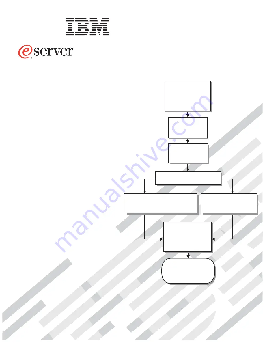
Install and start
the blade servers
Install addtional
applications, such as
IBM systems management
software and IBM
ServeRAID programs
Server is ready to use.
Go to the Server Support
flowchart to register
and profile your server.
Install options:
• Drives
• Microprocessors
• Storage expansion unit
• Memory
• I/O expansion
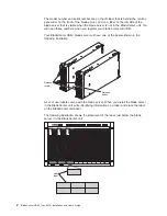
If the BladeCenter
or
is not installed in a
rack, install it now
BladeCenter T
BladeCenter HS40
Type 8839
Using Server Guide
Go to the Web for
www.ibm.com/pc/support.html
instructions
http://
Using the NOS
installation instructions
at www.ibm.com/pc/support
Install an operating system
(choose one method)
Summary of Contents for HS40 - BladeCenter - 8839
Page 3: ...BladeCenter HS40 Type 8839 Installation and User s Guide ERserver...
Page 8: ...vi BladeCenter HS40 Type 8839 Installation and User s Guide...
Page 76: ...62 BladeCenter HS40 Type 8839 Installation and User s Guide...
Page 90: ...76 BladeCenter HS40 Type 8839 Installation and User s Guide...
Page 114: ...100 BladeCenter HS40 Type 8839 Installation and User s Guide...
Page 118: ...104 BladeCenter HS40 Type 8839 Installation and User s Guide...
Page 119: ......
Page 120: ...Part Number 90P3102 Printed in USA 1P P N 90P3102...


