background image

IBM System Storage SAN06B-R

Installation, Service, and User Guide

Service information: 2498 / R06

GC27-2270-02

Read Before Using

This product contains software that is licensed under written license agreements. Your use of such software is subject to
the license agreements under which they are provided.

Summary of Contents for SAN06B-R

Page 1: ...and User Guide Service information 2498 R06 GC27 2270 02 Read Before Using This product contains software that is licensed under written license agreements Your use of such software is subject to the...

Page 2: ......

Page 3: ...IBM System Storage SAN06B R Installation Service and User Guide Service information 2498 R06 GC27 2270 02...

Page 4: ...MACHINES CORPORATION PROVIDES THIS PUBLICATION AS IS WITHOUT WARRANTY OF ANY KIND EITHER EXPRESS OR IMPLIED INCLUDING BUT NOT LIMITED TO THE IMPLIED WARRANTIES OF MERCHANTABILITY OR FITNESS FOR A PART...

Page 5: ...p publications order Search by form number or title For more information about IBM SAN products see the following Web site www ibm com servers storage san IBM Redbooks often provide in depth informati...

Page 6: ...e same information as the colors of the LEDs v Industry standard devices for ports and connectors v Management of the product through management applications is available through Web and Graphical Use...

Page 7: ...u have comments or suggestions for improving this document send us your comments by email to starpubs us ibm com Be sure to include the following information v Exact publication title v Form number fo...

Page 8: ...vi SAN06B R Installation Service and User Guide...

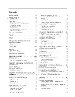
Page 9: ...tch date and time 19 Configuring FCIP and Fibre Channel routing services 20 Installing SFPs 21 Connecting cables 21 Verifying correct operation of the switch 22 Backing up the configuration 23 Managin...

Page 10: ...n Statement 52 Japan VCCI Council Class A Statement 52 Japan Electronics and Information Technology Industries Association JEITA Statement 52 Korea Communications Commission KCC Statement 52 Russia El...

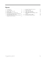
Page 11: ...brackets to the switch 12 7 Mounting the fixed portion of the rail and the locking brackets to the rack 13 8 Inserting slides into the rack rails 14 9 LEDs on port side 26 10 Nonport side components 2...

Page 12: ...x SAN06B R Installation Service and User Guide...

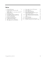
Page 13: ...atterns 28 11 GbE optical port status LED patterns 28 12 GBE copper port status LED patterns 29 13 Power supply fan status LED patterns 30 14 Switch dimensions 37 15 Power supply specifications 38 16...

Page 14: ...xii SAN06B R Installation Service and User Guide...

Page 15: ...the sections that follow v Note These notices provide important tips guidance or advice v Attention notices on page xviii These notices indicate potential damage to programs devices or data v Caution...

Page 16: ...ngerous voltage on the metal shell If any of the conditions are not as described STOP Ensure the improper voltage or impedance conditions are corrected before proceeding D003 DANGER An electrical outl...

Page 17: ...e v Connect any equipment that will be attached to this product to properly wired outlets v When possible use one hand only to connect or disconnect signal cables v Never turn on any equipment when th...

Page 18: ...oving parts nearby A hazardous condition due to the use of a laser in the product Laser symbols are always accompanied by the classification of the laser as defined by the U S Department of Health and...

Page 19: ...wing devices CD ROM drive DVD ROM drive DVD RAM drive or laser module which are Class 1 laser products Note the following information v Do not remove the covers Removing the covers of the laser produc...

Page 20: ...GER Multiple power cords The product might be equipped with multiple power cords To remove all hazardous voltages disconnect all power cords L003 DANGER Hazardous voltage present Voltages present cons...

Page 21: ...tomer to ensure that the outlet is correctly wired and grounded to prevent an electrical shock R001 part 1 of 2 CAUTION v Do not install a unit in a rack where the internal rack ambient temperatures w...

Page 22: ...that the route that you choose can support the weight of the loaded rack cabinet Refer to the documentation that came with your rack cabinet for the weight of a loaded rack cabinet Verify that all do...

Page 23: ...r translated environmental statements and information regarding product recycling and disposal This document may be provided either in printed version or on the product documentation CD See Removing t...

Page 24: ...xxii SAN06B R Installation Service and User Guide...

Page 25: ...ibm com shop publications order Search by publication title or publication number Newer versions may also be available through the IBM Support Portal www ibm com supportportal Enter your product mach...

Page 26: ...ed Table 2 Brocade and IBM product and model number matrix Brocade product name IBM product name IBM machine type and model number Brocade 6520 SAN96B 5 2498 Models F96 and N96 Brocade 6505 SAN24B 5 2...

Page 27: ...ionality can be used over the FCIP link Fabrics connected through FCIP merge if the ports are configured as VE_Ports and do not merge if one end of the connection is configured as a VEx_Port If VE_Por...

Page 28: ...es Open Systems Tape Pipelining over FCIP tunnel No Yes FICON CUP No Yes3 1 Requires IR license 2 Requires Advanced Extension license 3 Requires FICON CUP license v Before the installation of the upgr...

Page 29: ...asing the internal switch buffers to help maintain performance on ISLs at distances v Adapative Networking provides a set of capabilities allowing high priority connections to obtain the bandwidth nec...

Page 30: ...side of the switch Figure 3 shows the nonport side of the switch which contain the combined power supplies and fans 1 Fan and power supply assembly 2 7 Fan assembly 1 2 Fan and power supply assembly...

Page 31: ...mand line interface CLI Up to two admin sessions and four user sessions simultaneously For more information see the Fabric OS Administrator s Guide and the Fabric OS Command Reference Ethernet preferr...

Page 32: ...6 SAN06B R Installation Service and User Guide...

Page 33: ...ntake vents facing a cool air aisle Verify that the ambient air temperature does not exceed 40 C 104 F and that the ambient humidity remains between 20 and 85 while the switch is operating This chapte...

Page 34: ...ectrical branch circuits with the following characteristics are available v Primary ac input 100 240 V ac 2 0A 47 to 63 Hz the switch autosenses input voltage v Correctly wired primary outlets with ci...

Page 35: ...ot including configuration Items required You need the following items to install the switch in a slide rail rack v Straight slot screwdriver v Rack space 1U of rack space v Two power cables that are...

Page 36: ...tch 1 3 Left rack mount bracket optional bracket for front of switch 1 4 Rack mounting bracket 3 hole 4 5 Nut clip M5 11 6 Screw 8 32 x 3 16 in zinc 11 7 Screw M5 x 12 11 8 Bracket to slide rack kit c...

Page 37: ...nstall the inner smaller slide on the switch chassis as Figure 4 on page 10 shows Attention If you use screws longer than 3 16 in you can damage the switch a Position the flat side of the inner rail a...

Page 38: ...nc screws see 6 in Figure 4 on page 10 c Repeat step 4a and step 4b for the right rack mount bracket on the right front corner of the switch chassis 5 Attach all four of the 3 hole rack mounting brack...

Page 39: ...locking ears b Attach the slides by using four M5 x 12 screws 7 see Figure 4 on page 10 c Repeat step 6a and step 6b for the other rail 7 Install the switch in the rack a Position the switch in front...

Page 40: ...ne of the following steps v Set the internet protocol IP address v Verify that the default IP address does not conflict with the existing IP addresses in the same network Cabling and setting up the sw...

Page 41: ...d can damage the optic fibers Items required for setup The following items are required for configuring and connecting the switch for use in a network and fabric v The switch installed and connected t...

Page 42: ...s one to three minutes to boot and complete the POST process The LED will then change to green Note Power is supplied to the switch as soon as the first power supply is connected and turned on 4 After...

Page 43: ...rver to set the IP address of the switch DHCP is enabled by default The switch supports both IPv4 and IPv6 Using DHCP to set the IP address When using DHCP the switch obtains its IP address subnet mas...

Page 44: ...that the switch is not being modified from any other connections during the configuration process Setting the switch domain ID Perform the following steps to set the switch domain ID 1 Log on to the...

Page 45: ...ones so changes will have to be reset manually switch admin date Fri Sep 29 17 01 48 UTC 2007 switch admin date 0927123007 Thu Sep 27 12 30 00 UTC 2007 switch admin Synchronizing local time with an ex...

Page 46: ...e parameters of the tsTimeZone command refer to the Fabric OS Command Reference Configuring FCIP and Fibre Channel routing services The ports on the switch are initially set to persistently disabled O...

Page 47: ...Ensure that both cable and transceiver are clean prior to installation c Position a transceiver so that it is oriented correctly and insert it into a port until it is firmly seated and the latching m...

Page 48: ...page 25 2 Run the portCfgPersistntEnable command to activate the FC ports for FC operation 3 Verify the correct operation of the switch by entering the switchShow command from the workstation This co...

Page 49: ...w7800 admin The configUpload command uploads the switch configuration to the server so that it is available for downloading to a replacement switch if necessary For specific instructions about how to...

Page 50: ...t The key is an encrypted form of the system WWN and the products licensed to run on this system 3 Enter the licenseAdd command followed by the license key enclosed in quotation marks as shown in the...

Page 51: ...he status LEDs might display solid amber or flash during boot POST or other diagnostic tests This is normal it does not indicate a problem unless the LEDs do not indicate a healthy state after all boo...

Page 52: ...pull out tab 15 GbE optical port 8 USB port 16 GbE dual color optical port LED Power status LED patterns The power status LED on the front of the switch see 2 in Figure 9 indicates the status of the...

Page 53: ...isplays steady amber during POST this is normal and does not indicate a fault Perform the following steps 1 Connect a serial cable to the system 2 Reboot the system 3 Check the failure indicated on th...

Page 54: ...data is flowing through the port No action required Steady amber Port is receiving light or signal carrier but it is not online yet No action required Slow flashing amber on 2 seconds then off 2 seco...

Page 55: ...workstation If the fault persists use the other copper port or the optical ports or contact IBM LEDs on the nonport side of the switch The LEDs on the nonport side of the switch provide status informa...

Page 56: ...colors To determine whether POST completed successfully and whether any errors were detected 1 Verify that the LEDs on the switch indicate that all components are healthy see LED activity on page 25...

Page 57: ...power cycle the switch CRU status The power supply fan assemblies are customer replaceable units CRUs which can be replaced without the use of special tools To determine the status of these CRUs use...

Page 58: ...ecified in the procedures Attention Before installing removing or replacing any component read and follow the Safety notices and labels on page xiii The switch has two power supply fan assemblies 1 1...

Page 59: ...one not being replaced has been powered on for at least four seconds and has a green LED 2 Power off the power supply fan being replaced by pressing the AC power switch to O 3 Unplug the power cord fr...

Page 60: ...lithium To avoid possible explosion do not burn or charge the battery Do not v Throw or immerse into water v Heat to more than 100 C 212 F v Repair or disassemble Exchange only with the IBM approved p...

Page 61: ...C362 C363 C364 C365 C366 C42 C43 C44 C45 C46 C47 C48 C172 C170 C169 C168 C171 C173 C201 C198 C197 C200 C199 C203 C202 C224 C228 C227 C226 C225 C267 C266 C268 C155 C265 C154 C153 C263 C264 C260 C262 C2...

Page 62: ...36 SAN06B R Installation Service and User Guide...

Page 63: ...imately 3 m long An RJ 45 to DB9 adaptor is also provided with the switch v One IEEE compliant RJ 45 connector on the port side of the switch for use with a serial console and 10 100 MB sec Ethernet v...

Page 64: ...e frequency 47 63 Hz BTU rating 590 BTU hr Inrush current Maximum of 60 amps for period between 10 150 ms Input line protection Both AC lines are fused Environmental requirements Table 16 lists the ac...

Page 65: ...km 6 2 mi 80 km 50 mi 4 Gbps 50 150 m 492 ft OM2 380 m 1 246 ft OM3 NA NA 62 5 70 m 230 ft NA NA 9 NA 10 km 6 2 mi NA 8 Gbps 50 50 m 164 ft OM2 150 m 492 ft OM3 NA NA 62 5 21 m 69 ft NA NA 9 NA 10 km...

Page 66: ...Gbps The 8 virtual FCIP Fibre Channel links over each physical Ethernet connection share this bandwidth Serial port specifications The serial port is located on the port side of the switch The switch...

Page 67: ...r needs Attention Use only transceivers that are supported for this product Only transceivers purchased from IBM are supported The use of transceivers that are not supported may cause data loss or cau...

Page 68: ...42 SAN06B R Installation Service and User Guide...

Page 69: ...m link errors They may also be due to v Configuration issues v Networking overload v Failures on storage device switch or server Assume for these procedures that the observed errors originate from lin...

Page 70: ...ive power is abnormally lower than the minimum receive specification of the transceiver It is also prudent to compare this receive power with those of neighboring transceivers For better accuracy it i...

Page 71: ...1 0 5 Power Rx max dB 0 or 3 1 N A N A 1 The maximum receive power specifications of some 2 Gbps LWL 10km transceivers can vary from 0dB to 3dB However most 2 Gbps 10km transceivers specify a maximum...

Page 72: ...aximum power levels are listed in Table 23 and can be used as a quick method to relieve concerns of over saturation Table 23 Maximum receive power of 2 Gbps LWL SFPs Vendor Part number Description Max...

Page 73: ...ocal law INTERNATIONAL BUSINESS MACHINES CORPORATION PROVIDES THIS PUBLICATION AS IS WITHOUT WARRANTY OF ANY KIND EITHER EXPRESS OR IMPLIED INCLUDING BUT NOT LIMITED TO THE IMPLIED WARRANTIES OF NON I...

Page 74: ...products was obtained from the suppliers of those products their published announcements or other publicly available sources IBM has not tested those products and cannot confirm the accuracy of perfor...

Page 75: ...arks of Adobe Systems Incorporated in the United States and or other countries Java and all Java based trademarks and logos are trademarks of Sun Microsystems Inc in the United States other countries...

Page 76: ...void the user s authority to operate the equipment This device complies with Part 15 of the FCC Rules Operation is subject to the following two conditions 1 this device may not cause harmful interfer...

Page 77: ...hen werden Warnung Dieses ist eine Einrichtung der Klasse A Diese Einrichtung kann im Wohnbereich Funk St rungen verursachen in diesem Fall kann vom Betreiber verlangt werden angemessene Ma nahmen zu...

Page 78: ...user may be required to take corrective actions Japan Electronics and Information Technology Industries Association JEITA Statement Japanese Electronics and Information Technology Industries Associati...

Page 79: ...A Statement Australia and New Zealand Class A Statement Attention This is a Class A product In a domestic environment this product might cause radio interference in which case the user might be requir...

Page 80: ...54 SAN06B R Installation Service and User Guide...

Page 81: ...cations 40 management port LED patterns 27 location 3 F fan assembly LED patterns 29 location 4 replacing 32 status 31 FCIP configuring 20 features 2 Fibre Channel ports configuring routing services 2...

Page 82: ...g site for installation 8 product specifications 37 pull out tab 3 R rack safety xix xx rack mount kit 9 10 read this first iii recycling xxi renaming chassis 18 switch 18 S safety labels xiii notices...

Page 83: ......

Page 84: ...Part Number 98Y5370 Printed in USA GC27 2270 02 1P P N 98Y5370...

Page 85: ...Spine information IBM System Storage SAN06B R SAN06B R Installation Service and User Guide Service information 2498 R06...

Reviews: