background image


®

ServeRAID M5014/M5015 
SAS/SATA Controllers

USER’S

GUIDE

M a y   2 0 1 2

Summary of Contents for ServeRAID M5014

Page 1: ...ServeRAID M5014 M5015 SAS SATA Controllers USER S GUIDE M a y 2 0 1 2...

Page 2: ...ion May 2012 Copyright International Business Machines Corporation 2012 All rights reserved US Government Users Restricted Rights Use duplication or disclosure restricted by GSA ADP Schedule Contract...

Page 3: ...erveRAID M Software User s Guide For information about the operating system drivers refer to the ServeRAID M Device Driver Installation User s Guide Audience This document assumes that the reader is f...

Page 4: ...the ServeRAID M5000 Series Battery Assembly describes the ServeRAID M5000 Series Battery Assembly and explains how it operates Chapter 5 Installing a ServeRAID M5000 Series Battery Assembly explains...

Page 5: ...ties to configure monitor and maintain the ServeRAID M controller and the storage related devices connected to them Safety Information This document contains translated caution and danger statements E...

Page 6: ...ntially lethal or extremely hazardous procedure step or situation Safety Instructions Use the following safety guidelines to help protect your computer system from potential damage and to ensure your...

Page 7: ...Preface vii...

Page 8: ...rface to remove any static charge your body may have accumulated In addition to the preceding precautions you can also take the following steps to prevent damage from electrostatic discharge When unpa...

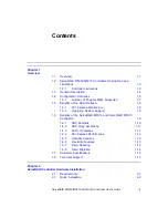
Page 9: ...ce 1 8 1 5 1 PCI Express Architecture 1 9 1 5 2 Operating System Support 1 9 1 6 Benefits of the ServeRAID M5014 and ServeRAID M5015 Controllers 1 9 1 6 1 SAS Features 1 10 1 6 2 SAS Array Limitations...

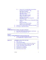
Page 10: ...ray Performance Features 3 6 3 3 3 Fault Tolerance 3 7 3 3 4 Power Supply Requirements for the ServeRAID M5014 M5015 Controllers 3 7 3 3 5 Operating and Non operating Conditions 3 8 3 3 6 Safety Chara...

Page 11: ...bly 6 13 6 3 Resolving a Configuration Mismatch 6 14 Chapter 7 ServeRAID M5000 Series Battery Assembly Specifications 7 1 ServeRAID M5000 Series Battery Assembly Specifications 7 1 7 2 Battery Life an...

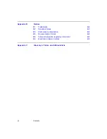
Page 12: ...1 Trademarks B 2 B 2 Important Notes B 3 B 3 Particulate contamination B 4 B 4 Documentation format B 5 B 5 Telecommunication regulatory statement B 5 B 6 Electronic emission notices B 5 Appendix C Gl...

Page 13: ...Connecting the ServeRAID M5014 M5015 Controller Internal Connectors to a Physical Drive 2 9 3 1 Card Layout for the ServeRAID M5014 M5015 RAID Controllers 3 2 5 1 ServeRAID M5000 Series Battery Assem...

Page 14: ...xiv Contents...

Page 15: ...veRAID M5015 SAS SATA Controllers Specifications 3 5 3 4 Array Performance Features 3 6 3 5 Fault Tolerance Features 3 7 3 6 Power Supply for the ServeRAID M5014 M5015 Controllers 3 8 6 1 Display BBU...

Page 16: ...xvi Contents...

Page 17: ...d ServeRAID M5015 Controllers Section 1 7 Hardware Specifications Section 1 8 Technical Support 1 1 Overview The ServeRAID M5014 and ServeRAID M5015 Serial Attached SCSI SAS Serial ATA II SATA II cont...

Page 18: ...Series Battery Assembly is pre installed on the ServeRAID M5015 controller to provide battery protected backup of cached memory The assembly provides protection of cached data which allows system buil...

Page 19: ...les communication with a SATA II device through an attached expander 1 2 ServeRAID M5014 M5015 Controllers Descriptions and Limitations The ServeRAID M5014 and ServeRAID M5015 controllers are availabl...

Page 20: ...architecture and provides a PCI Express x8 interface The controllers integrate eight high performance SAS SATA II PHYs and a PCI Express bus master DMA core Each of the eight PHYs is capable of 6 0 G...

Page 21: ...elector for dual port drives Each port on the ServeRAID M5015 controller supports SAS devices SATA II devices or both using SSP SMP STP and SATA II SSP enables communication with other SAS devices SAT...

Page 22: ...PSBRAM nonvolatile static random access memory NVSRAM and Flash ROM Figure 1 1 Example of a SAS Direct Connect Application Figure 1 2 shows an example of a ServeRAID controller configured with an LSIS...

Page 23: ...ID level can be assigned to each virtual disk Table 1 1 shows the minimum number and the maximum number of drives required for each RAID level LSISASx12 Flash ROM NVSRAM SRAM I2 C UART LSISASx12 SAS S...

Page 24: ...es improved performance simplified cabling smaller connectors lower pin count and lower power requirements when compared to parallel SCSI The ServeRAID M5014 and ServeRAID M5015 controllers leverage a...

Page 25: ...em Support To check for the latest list of supported operating systems and to download the drivers for those operating systems see http www ibm com systems support The ServeRAID M5014 and ServeRAID M5...

Page 26: ...firmware is stored in flash ROM for easy upgrade 1 6 1 SAS Features The following list describes the SAS features of the ServeRAID M5014 and ServeRAID M5015 controllers Provides eight fully independen...

Page 27: ...expanders However the actual number of drives that you can attach depends on the limits listed in Table 1 2 rather than by the actual RAID volume capacity The maximum numbers in Table 1 2 depend on ho...

Page 28: ...I Express Performance The following list describes the PCI Express performance features of the ServeRAID M5014 and ServeRAID M5015 controllers Provides a PCI Express interface that Supports a dedicate...

Page 29: ...Allows mixed connections to SAS targets or SATA II targets Leverages compatible connectors for SAS connections and SATA II connections Allows grouping of up to four PHYs in a single quad port to form...

Page 30: ...inserted correctly b Close the cabinet of the host system Step 6 Reconnect the power cords to the system Step 7 Turn on the power to the system The controller then detects the RAID configuration from...

Page 31: ...3 Open the host system following the instructions in the host system technical documentation Step 4 Remove the SAS cable connectors from the internal drives that you want to migrate a Make sure that...

Page 32: ...vices such as drives and expanders Ports Eight internal Data Transfer Rate Up to 6 Gb s per phy Bus PCI Express 2 0 Cache Function Write back write through adaptive read ahead non read ahead read ahea...

Page 33: ...Technical Support 1 17 1 8 Technical Support For information about the technical support available for this product see Appendix A Getting Help and Technical Assistance...

Page 34: ...1 18 Overview...

Page 35: ...ction 2 3 Detailed Installation Section 2 4 SAS Device Cables Section 2 5 After Installing the Controller 2 1 Requirements The following items are required for installation A ServeRAID M5014 or ServeR...

Page 36: ...to it Make sure that the cables you use conform to all specifications Step 4 Perform a safety check a Make sure that all cables are properly attached b Make sure that the controller is installed corre...

Page 37: ...Step 4 Review the Controller Limitations Review Section 1 2 1 Controller Limitations before you install the controller in the system Step 5 Check the Battery Backup Unit Make sure that the ServeRAID M...

Page 38: ...e Note See the documentation for the external devices for pre installation configuration requirements Step 8 Connect the SAS Devices the SATA II Devices or Both to the Controller Use SAS cables to con...

Page 39: ...irmware Interface uEFI no BIOS message displays Press F1 to enter System Setup Refer to your system user s guide for specific configuration information Under other interfaces or operating systems a BI...

Page 40: ...erveRAID M Support CD Be sure to use the latest Service Packs provided by the operating system manufacturer and to review the readme file that accompanies the driver 2 4 SAS Device Cables This section...

Page 41: ...with internal connectors to the host receptable connector on a backplane A SATA II connector consists of a signal connector and a power connector Figure 2 3 SATA II Connectors Physical Drive Connector...

Page 42: ...er which the SATA II connector does not have Note SAS backplane connectors can accept SAS physical drives or SATA II physical drives but SATA II backplane connectors cannot accept SAS drives Figure 2...

Page 43: ...nnector on the internal cable into the internal connector on the controller Step 2 Plug the connector on the other end of the internal cable into the connector on the SAS physical drive or the SATA II...

Page 44: ...ller you must configure it and install the operating system driver The ServeRAID M Software User s Guide instructs you on the configuration options and how to set them on your controller The ServeRAID...

Page 45: ...ion 3 3 Technical Specifications 3 1 ServeRAID M5014 M5015 SAS SATA Controller Descriptions The ServeRAID M5014 and ServeRAID M5015 SAS SATA controllers are dual PHY SAS PCI Express adapters and are u...

Page 46: ...M5014 M5015 RAID Controllers Table 3 1 ServeRAID M5014 and ServeRAID M5015 Controllers Connectors Connector Description Type Comments JT1 Write pending Indicator dirty cache LED connector 2 pin connec...

Page 47: ...JT11 IPMI style SMBus System Manage ment I2 C header 3 pin shielded header Provides enclosure management support JT12 Individual Drive Fault LED header for Eight Phys 0 7 16 pin connector Indicates d...

Page 48: ...nd implementation of the ServeRAID M5014 and ServeRAID M5015 SAS SATA controllers minimize electromagnetic emissions susceptibility to radio frequency energy and the effects of electrostatic discharge...

Page 49: ...cification ServeRAID M5014 M5015 SAS SATA Controllers Processor PCI Express Host Controller to PCI Secondary I O Controller LSISAS2108 ROC device with Integrated PowerPC processor Operating Voltage 3...

Page 50: ...olatile Random Access Memory NVRAM 32 Kbytes for storing RAID configuration Table 3 3 ServeRAID M5014 and ServeRAID M5015 SAS SATA Controllers Specifications Cont Specification ServeRAID M5014 M5015 S...

Page 51: ...3 While sitting idle at the DOS prompt Table 3 5 Fault Tolerance Features Specification ServeRAID M5015 SAS SATA Controllers Support for SMART1 1 The Self Monitoring Analysis and Reporting Technology...

Page 52: ...3 5 Operating and Non operating Conditions The operating thermal and atmospheric conditions for the ServeRAID M5014 and ServeRAID M5015 SAS SATA controllers are Relative humidity range is 5 to 90 non...

Page 53: ...M5015 SAS SATA controllers meet or exceed the requirements of UL flammability rating 94 V0 Each bare board is also marked with the supplier name or trademark type and UL flammability rating The board...

Page 54: ...3 10 ServeRAID M5014 M5015 SAS SATA Controller Characteristics...

Page 55: ...data can be lost if the AC power fails before it has been written to the storage device This risk factor is eliminated when the controller has an onboard battery assembly The ServeRAID M5000 Series Ba...

Page 56: ...le explosion do not burn Exchange only with the IBM approved part Recycle or discard the battery as instructed by local regulations In the United States IBM has a process for the collection of this ba...

Page 57: ...tive Devices Follow the ESD recommended practices in the latest revision of IPC A 610 The battery in the battery assembly must charge for at least six hours during fast charge under normal operating c...

Page 58: ...ry assembly mounts directly to the controller using a small board to board connector daughtercard The following figure displays the top view and the bottom view of the card The top side is the side yo...

Page 59: ...nplug the power cords 2 Remove the cover from the computer according to the instructions in the system user s manual so you can access the controller 3 Ground yourself before you touch the controller...

Page 60: ...5 Secure the battery assembly to the controller with the screws and the standoffs in the three screwholes The standoffs are threaded at both ends and a screw goes into each end 6 Use the Phillips head...

Page 61: ...wing figure Figure 5 3 Installing the ServeRAID M5014 Controller 8 Attach the controller to the computer chassis with the bracket screw 9 Attach the cables as needed to the connectors on the controlle...

Page 62: ...5 6 Installing a ServeRAID M5000 Series Battery Assembly...

Page 63: ...y Section 6 3 Resolving a Configuration Mismatch You can monitor the battery status temperature voltage and so on in these MegaRAID utility programs WebBIOS Configuration Utility MegaCLI Command Line...

Page 64: ...5000 Series Battery Assembly with the WebBIOS Configuration Utility The WebBIOS CU is a web based utility for configuring and managing RAID volumes Its operation is independent of the operating system...

Page 65: ...es Screen f 4 Click Next to view the second Controller Properties screen The second Controller Properties screen appears as shown in the following figure The Battery Backup field at the top left of th...

Page 66: ...rties Figure 6 3 Battery Module Screen Most of the Battery Module properties are view only and are self explanatory In the lower right corner of the screen are the Auto Learn options A learning cycle...

Page 67: ...Learn Delay Interval field You can delay the start of the learn cycles for up to 168 hours 7 days 4 Click Go 6 1 1 2 Setting the Learn Mode You can start battery learn cycles manually or automatically...

Page 68: ...lay complete information about the BBU for the selected controller s 6 1 2 2 Display BBU Status Information Use the command in Table 6 2 to display complete information about the status of the BBU suc...

Page 69: ...o Fully Charged Yes No Discharging Yes No Initialized Yes No Remaining Time Alarm Yes No Remaining Capacity Alarm Yes No Discharge Terminated Yes No Over Temperature Yes No Charging Terminated Yes No...

Page 70: ...pacity Info for Adapter x Relative State of Charge xx Absolute State of Charge xx Remaining Capacity xx mAh Full Charge Capacity xx mAh Run Time to Empty xxx Min Average Time to Empty xxx Min Average...

Page 71: ...e on the selected controller s This saves battery power consumption Table 6 5 Display Current BBU Properties Convention MegaCli AdpBbuCmd GetBbuProperties aN a0 1 2 aALL Description Displays current p...

Page 72: ...ery backup unit BBU perform the following steps 1 Click the Physical tab to open the physical view 2 Select the BBU icon in the left panel 3 Click the Properties tab The BBU properties such as the bat...

Page 73: ...ntage of its current state of charge and the estimated time until it will be depleted The current BBU temperature voltage current and remaining capacity If the battery is charging the estimated time u...

Page 74: ...erties The BBU operations screen appears 4 Select one of the two automatic learn cycles Select the Enable radio button to enable an automatic learn cycle Select the Disable radio button to disable an...

Page 75: ...Assembly every three years When you install a new battery assembly the battery recharge cycle counter for the battery assembly is automatically set to zero For instructions on installing the battery a...

Page 76: ...the NVRAM and the configuration data on the drives are different To resolve this update the configuration data in the NVRAM with the data from the physical disk To update the configuration data follow...

Page 77: ...t pre installed on the ServeRAID M5014 controller but can be installed if desired See Section 5 1 Installing the ServerRAID M5000 Series Battery Assembly on a Controller for installation instructions...

Page 78: ...ance replace the battery backup unit every three years or as advised by the warning messages The data retention time shown in Table 7 2 is approximate They can vary based on a number of factors includ...

Page 79: ...the number of discharge cycles Number of DIMMs installed and the number of chips on the DIMMs DRAM size Table 7 2 Reference Data Retention Times Data Retention Times 48 hours for 512 Mbytes using five...

Page 80: ...7 4 ServeRAID M5000 Series Battery Assembly Specifications...

Page 81: ...r The following figure shows the ServeRAID M5000 Series Advanced Feature Key Figure 8 1 M5000 Series Advanced Feature Key Note It is important to back up any data before you make a change in system co...

Page 82: ...Ground yourself before you touch the controller or the Advanced Feature Key 4 Remove the Advanced Feature Key from the package 5 Hold the Advanced Feature Key so that the J1 connector is up and the co...

Page 83: ...nce or just want more information about IBM products you will find a wide variety of sources available from IBM to assist you Use this information to obtain additional information about IBM and IBM pr...

Page 84: ...ly provide a solution to your problem and ensure that you receive the level of service for which you might have contracted o Hardware and Software Maintenance agreement contract numbers if applicable...

Page 85: ...ome documents are available through the IBM Publications Center at http www ibm com shop publications order On the World Wide Web up to date information about IBM systems optional devices services and...

Page 86: ...hnical documents search for information and downloads and access various administrative services Through IBM Support Line you can get telephone assistance for a fee with usage configuration and softwa...

Page 87: ...IBM Taiwan product service A 5 A 8 IBM Taiwan product service...

Page 88: ...A 6 Getting Help and Technical Assistance...

Page 89: ...ServeRAID M5014 M5015 SAS SATA Controllers User s Guide B 1 Appendix B Notices...

Page 90: ...band Engine is a trademark of Sony Computer Entertainment Inc in the United States other countries or both and is used under license therefrom Intel Intel Xeon Itanium and Pentium are trademarks or re...

Page 91: ...um internal hard disk drive capacities assume the replacement of any standard hard disk drives and population of all hard disk drive bays with the largest currently supported drives that are available...

Page 92: ...pair or replacement of devices or parts on implementation of appropriate remedial measures to mitigate such environmental contamination Implementation of such remedial measures is a customer responsib...

Page 93: ...nwallis Road P O Box 12195 Research Triangle Park North Carolina 27709 2195 U S A In the request be sure to include the publication part number and title When you send information to IBM you grant IBM...

Page 94: ...B 6 Notices...

Page 95: ...Electronic emission notices B 7...

Page 96: ...B 8 Notices...

Page 97: ...ie 2004 108 EG f r Ger te der Klasse A Dieses Ger t ist berechtigt in bereinstimmung mit dem Deutschen EMVG das EG Konformit tszeichen CE zu f hren Verantwortlich f r die Einhaltung der EMV Vorschrift...

Page 98: ...VCCI If this equipment is used in a domestic environment radio interference may occur in which case the user may be required to take corrective actions This is electromagnetic wave compatibility equi...

Page 99: ...s computer monitor keyboard and peripheral devices that make up a computer system or the software settings that allow the hardware components to communicate with each other device driver A program tha...

Page 100: ...only from virtual disks with redundancy RAID levels 1 5 6 10 50 and 60 not RAID level 0 and the hot spare must have sufficient capacity internal SAS device A SAS device installed inside the computer...

Page 101: ...of multiple independent physical disks managed together to yield higher reliability and or performance exceeding that of a single physical disk The RAID array appears to the controller as a single sto...

Page 102: ...emory to store data They have no moving parts and are faster and more reliable than hard disk drives HDDs SSP Acronym for Serial SCSI Protocol SSP enables communication with other SAS devices Each PHY...

Page 103: ...space consumed by a stripe is the same on each disk included in the stripe The portion of a stripe that resides on a single disk is a strip Striping by itself does not provide data redundancy striping...

Page 104: ...C 6 Glossary of Terms and Abbreviations...

Page 105: ......

Page 106: ...Part number 81Y1027...

Reviews: