background image

IBM TotalStorage LTO Ultrium 2 Tape Drive
Models T400 and T400F

Setup, Operator, and Service Guide

GA32-0455-00

Summary of Contents for T400

Page 1: ...IBM TotalStorage LTO Ultrium 2 Tape Drive Models T400 and T400F Setup Operator and Service Guide GA32 0455 00...

Page 2: ......

Page 3: ...IBM TotalStorage LTO Ultrium 2 Tape Drive Models T400 and T400F Setup Operator and Service Guide GA32 0455 00...

Page 4: ...s to the IBM TotalStorage LTO Ultrium 2 Tape Drive Models T400 and T400F Setup Operator and Service Guide and to all subsequent releases and modifications until otherwise indicated in new editions Cop...

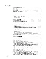
Page 5: ...Device Drivers 9 Chapter 2 Specifications 11 Chapter 3 Installing the Tape Drive 13 Rear View of the SCSI Drive 14 Rear View of the Fibre Channel Drive 15 Step 1 Unpack the Drive 16 Step 2 Remove Powe...

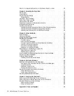
Page 6: ...pection 52 Handle the Cartridge Carefully 53 Examples of Cartridge Problems 54 Repositioning or Reattaching a Leader Pin 55 Repositioning a Leader Pin 55 Reattaching a Leader Pin 57 Environmental and...

Page 7: ...Drive 97 Notices 101 Trademarks 101 Electronic Emission Notices 102 Special Considerations for Electromagnetic Compatibility 102 IBM TotalStorage LTO Ultrium 2 Tape Drive Models T400 and T400F 102 Ge...

Page 8: ...vi IBM TotalStorage LTO Ultrium 2 Tape Drive...

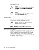
Page 9: ...tage on metal parts of the system or the products that attach to the system It is the customer s responsibility to ensure that the outlet is correctly wired and grounded to prevent an electrical shock...

Page 10: ...w Attention If you use a power screwdriver to perform this procedure it could destroy the tape Attention Do not operate the Ultrium 2 Tape Drive in a poor air quality environment Laser Safety and Comp...

Page 11: ...adapter cards and tells how to configure servers to use the device driver with the Ultrium family of devices v IBM Ultrium Device Drivers Programming Reference GC35 0483 supplies information to applic...

Page 12: ...x IBM TotalStorage LTO Ultrium 2 Tape Drive...

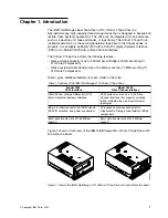
Page 13: ...ate of 35 MB per second 70 MB assuming 2 1 LTO Data Compression Table 1 gives additional features for each model of the drive Table 1 Features of the IBM TotalStorage LTO Ultrium 2 Tape Drive Model T4...

Page 14: ...ulates which of the two data rates at which to operate For example if the server transfers data at 60 MB s on the host bus at 2 1 compression its net data rate is 30 MB s The drive will then dynamical...

Page 15: ...ive on page 13 Table 2 Supported servers and operating systems for SCSI and Fibre Channel attachment Supported Servers Supported Operating Systems IBM AS 400 or ERserver iSeries OS 400 IBM RS 6000 RS...

Page 16: ...atible with older SCSI technology and is capable of data transmission at 160 MB s Ultra160 SCSI uses the three management features of the Ultra3 SCSI standard that specifically affect data transfer ra...

Page 17: ...an attach an Ultrium 2 Tape Drive to an active SCSI bus However the preferred and safest method of adding removing or resetting a drive is to power off the system When adding removing or resetting a d...

Page 18: ...tatus connector see Step 4 Change the Link Services of the Drive optional on page 24 the Ultrium 2 Tape Drive automatically configures to an L_port or an N_port when it boots The type of port to which...

Page 19: ...e listed in Table 5 on page 21 and Table 6 on page 22 You can set an AL_PA by using one of two methods known as soft addressing or hard addressing Soft addressing allows the drive to dynamically arbit...

Page 20: ...422 interface For instructions refer to the documentation for your tape library Physical Characteristics of the Fibre Channel Interface The Ultrium 2 Tape Drive attaches to Open Systems servers by usi...

Page 21: ...ftp ftp software ibm com storage devdrvr ftp 207 25 253 26 storage devdrvr v Using an IBM FTP site enter the following specifications FTP site ftp software ibm com IP Addr 207 25 253 26 Userid anonymo...

Page 22: ...10 IBM TotalStorage LTO Ultrium 2 Tape Drive...

Page 23: ...12 Vdc 10 Power supply current for 5 Vdc see Note 2 1 3 A minimum 1 9 A minimum 3 1 A maximum 3 7 A maximum Power supply current for 12 Vdc see Note 2 0 2 A minimum 0 2 A minimum 1 1 A maximum 1 1 A m...

Page 24: ...0 to 60 C 40 to 140 F Relative humidity noncondensing 20 to 80 10 to 90 10 to 90 Wet bulb temperature 26 C 78 8 F 26 C 78 8 F 26 C 78 8 F Notes 1 Measured at the drive s power connector 2 The 5 Vdc an...

Page 25: ...ible remove the Ultrium 2 Tape Drive from its static protective packaging and install it directly into an enclosure without setting it down When this is not possible place the tape drive s packaging o...

Page 26: ...SCSI connector 3 SCSI ID connector 4 Power connector 5 Library Drive Interface LDI or RS 422 interface connector Figure 2 Rear view of the IBM TotalStorage LTO Ultrium 2 Tape Drive Model T400 SCSI dr...

Page 27: ...ifier LID status connector 4 Fibre Channel FC configuration status connector 5 Fibre Channel connector 6 Library Drive Interface LDI or RS 422 interface connector Figure 3 Rear view of the IBM TotalSt...

Page 28: ...dry warm the drive more quickly by powering it on for 30 minutes Use a diagnostic tape to test the drive before inserting a tape that contains data v If the drive is hotter than its operating environ...

Page 29: ...ting the SCSI ID Setting the SCSI ID with Jumpers You can set the SCSI ID on the Ultrium 2 Tape Drive by installing 2 mm jumpers on the drive s SCSI ID connector see 3 in Figure 2 on page 14 Your tape...

Page 30: ...rary you can issue a command from the library to set the drive s SCSI ID through the LDI interface Make sure that the SCSI ID is set to 15 see Figure 5 When configured to accept its SCSI ID through th...

Page 31: ...the AL_PA by arbitrating it with other devices on the loop Valid LIDs and their corresponding AL_PAs are provided in this section Note A Loop ID is part of a contiguous range of values valid AL_PA va...

Page 32: ...e communication problems across the fiber cable If the drive is installed in an enclosure pins 5 and 6 may be used to support external indicators such as light emitting diodes LEDs on the enclosure No...

Page 33: ...5 2A G G G D4 B G G G A3 2B G G G G D3 C G G 9F 2C G G G D2 D G G G 9E 2D G G G G D1 E G G G 9D 2E G G G G CE F G G G G 9B 2F G G G G G CD 10 G 98 30 G G CC 11 G G 97 31 G G G CB 12 G G 90 32 G G G CA...

Page 34: ...6 for its corresponding LID __ 2 Locate the LID status connector on the drive see 2 in Figure 6 on page 20 __ 3 Place jumpers on pins 1 through 7 as shown in Table 6 or on pin 8 Table 6 ID settings th...

Page 35: ...44 G G 35 63 G G G G 6B 45 G G G 34 64 G G G 6A 46 G G G 33 65 G G G G 69 47 G G G G 32 66 G G G G 67 48 G G 31 67 G G G G G 66 49 G G G 2E 68 G G G 65 4A G G G 2D 69 G G G G 63 4B G G G G 2C 6A G G G...

Page 36: ...in 9 is ground To change the type of topology and the speed of the Fibre Channel drive __ 1 Determine the type of topology in which you want to operate the Ultrium 2 Tape Drive and refer to Table 7 fo...

Page 37: ...NL_Port the drive automatically selects and configures the topology X X G G X Notes 1 G means that the pin is jumpered to ground 2 means that the pin is not jumpered 3 X means that the setting of the...

Page 38: ...compartment faces the tape load compartment of the enclosure __ 3 Insert two 6 32 screws into the mounting holes 2 on the side brackets of the chassis Attention When inserted into the Ultrium 2 Tape...

Page 39: ...the status light is recessed and the light is not visible until lit To ensure that the drive is receiving power watch for the following while turning on the power to the enclosure v The single charact...

Page 40: ...the Device Drivers For information about installing device drivers refer to the documentation for your enclosure Step 11 Connect the External SCSI or Fibre Channel Interface to the Server Perform one...

Page 41: ...g up to 61 m 200 ft For ordering information see Table 16 on page 95 __ 2 Run the appropriate Fibre Channel attachment verification procedure from your server for instructions refer to the IBM Ultrium...

Page 42: ...30 IBM TotalStorage LTO Ultrium 2 Tape Drive...

Page 43: ...the Ultrium 2 Tape Drive refer to Figure 9 which shows the front of the unit 1 Status light 2 Unload button 3 Single character display 4 Single red dot Figure 9 Front view of the IBM TotalStorage LTO...

Page 44: ...completes the recovery and is ready for a read or write operation To eject the cartridge press the unload button Amber Solid The tape drive is powering on is resetting or is in maintenance mode For i...

Page 45: ...cter Display The Ultrium 2 Tape Drive features an LED 3 in Figure 9 on page 31 that presents a single character code for v Diagnostic or maintenance functions v Error conditions and informational mess...

Page 46: ...e write protect switch faces you see 1 in Figure 10 4 Slide the cartridge into the tape load compartment Notes a If the cartridge is already in an ejected position and you want to reinsert it remove t...

Page 47: ...ormation to the cartridge memory Cleaning the Drive Head Attention To clean the drive head use the IBM LTO Ultrium Cleaning Cartridge the IBM TotalStorage Cleaning Cartridge Ultrium LTO 2 or an IBM ap...

Page 48: ...ou cycle past 1 continue to press the unload button until it redisplays 4 To select the function press and hold the unload button for 3 seconds After you select the function 1 flashes the drive runs d...

Page 49: ...e drive posts an error code to the single character display to resolve the error see Table 15 on page 67 The drive then unloads the FMR tape and exits maintenance mode Function Code 3 Create FMR Tape...

Page 50: ...mode Simply press and hold the unload button for 10 seconds Function Code 5 Copy the Drive Dump to Tape at Beginning of Tape Causes the tape drive to copy data from a drive dump captured with Function...

Page 51: ...ve s SCSI connector Place a terminator on one end of the Y cable and the wrap plug on the other end 1 Ensure that the drive does not contain a cartridge 2 Within a 1 5 second interval press the unload...

Page 52: ...the Circuitry at the Drive s Fibre Channel Connector 6 To select the function press and hold the unload button for 3 seconds After you select the function the tape drive automatically starts the test...

Page 53: ...locate 9 in Table 15 on page 67 Function Code 8 Convert FMR Tape to Scratch Tape Causes the tape drive to erase the field microcode replacement FMR data on a scratch data cartridge and rewrite the ca...

Page 54: ...the tenth error code displays 0 displays if there are no errors in the log and the drive exits maintenance mode Function Code A Clear Error Code Log Causes the tape drive to erase the contents of the...

Page 55: ...Code F Fast Read Write Test Causes the tape drive to perform tests to ensure that the drive can read from and write to tape This diagnostic performs fewer tests than the Run Tape Drive Diagnostics tes...

Page 56: ...second to once per second The test continues to the end of its loop and then stops The tape drive then rewinds and unloads the cartridge displays 0 and exits maintenance mode v If an error is detecte...

Page 57: ...e different firmware images When you update the tape drive s firmware by using the SCSI or Fibre Channel interface the procedure varies depending on whether your server uses an IBM tape device driver...

Page 58: ...in maintenance mode 3 Press the unload button once per 1 5 seconds until 2 displays then press and hold the button for 3 seconds When C flashes the drive is waiting for a cartridge 4 Insert the FMR ta...

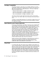
Page 59: ...ge compatibility for the Ultrium 2 Tape Drive is as follows v Reads and writes Generation 2 cartridges to Generation 2 format v Reads and writes Generation 1 cartridges to Generation 1 format v Does n...

Page 60: ...data is written The IBM TotalStorage LTO Ultrium 200 GB Data Cartridge includes a Linear Tape Open Cartridge Memory LTO CM chip 1 in Figure 11 on page 47 that contains information about the cartridge...

Page 61: ...enable your Generation 1 drive to use the cartridge simply download and install the latest drive firmware for instructions see Updating the Firmware on page 45 The drive itself determines when a head...

Page 62: ...e can interfere with the reliability of the drive and may void the warranties of the drive and the cartridge Before inserting a tape cartridge inspect the cartridge case cartridge door and write prote...

Page 63: ...dge in a jewel case v Use only a recommended shipping container that securely holds the cartridge in its jewel case during transportation Ultrium Turtlecases by Perm A Store have been tested and found...

Page 64: ...for Tape Cartridges on page 62 Perform a Thorough Inspection After purchasing a cartridge and before using it perform the following steps v Inspect the cartridge s packaging to determine potential ro...

Page 65: ...re that the leader pin is properly seated in the pin retaining spring clips see 2 in Figure 16 on page 55 If the leader pin has become dislodged go to Repositioning or Reattaching a Leader Pin on page...

Page 66: ...y procedures to minimize chances of data loss Example Split Cartridge Case The cartridge s case is damaged There is a high possibility of media damage and potential loss Perform the following steps 1...

Page 67: ...u must remove more than 7 meters 23 feet of leader tape The sections that follow describe each procedure Repositioning a Leader Pin A leader pin that is improperly seated inside a cartridge can interf...

Page 68: ...ps in the seam of the cartridge 4 Attention If gaps exist do not continue with this procedure and do not use the cartridge Instead contact your OEM Product Application Engineer PAE 4 Close the cartrid...

Page 69: ...ies see 3 in Figure 19 Leader pins and C clips Attention v Use only the IBM Leader Pin Reattachment Kit to reattach the leader pin to the tape Other methods of reattaching the pin will damage the tape...

Page 70: ...0 to the cartridge 2 so that the tool s hook 3 latches into the cartridge s door 4 Pull the tool back to hold the door open then slide the tool onto the cartridge Open the tool s pivot arm 5 Figure 20...

Page 71: ...d it from the cartridge 4 Remove the rewind tool by pulling it away from the cartridge Set the tool and the cartridge aside 5 On the leader pin 1 in Figure 22 locate the open side of the C clip 2 The...

Page 72: ...he tape over the leader pin and hold it with your fingers see Figure 23 Note Use care to ensure that the tape is centered over the leader pin Failure to properly center the tape on the pin will cause...

Page 73: ...leader pin is latched by the pin retaining spring clips on each end of the leader pin 15 Remove the rewind tool 16 Remove the leader pin attach tool by lifting its end up and away from the cartridge A...

Page 74: ...contaminants and physical damage Ship the cartridge in a shipping container that has enough packing material to cushion the cartridge and prevent it from moving within the container Table 10 gives the...

Page 75: ...ak field over the entire space that the cartridge occupies Degaussing makes the cartridge unusable If you burn the cartridge and tape ensure that the incineration complies with all applicable regulati...

Page 76: ...44 0 1245 322380 http www edpeurope com media_labelling htm Dataware LTO 2 only 7570 Renwick Houston TX 77081 U S A Telephone 800 426 4844 http www datawarelabels com Dataware Labels Europe Heubergstr...

Page 77: ...ges the tape drive is defective Replace the tape drive see Removing a SCSI Tape Drive from an Enclosure on page 83 or Removing a Fibre Channel Tape Drive from an Enclosure on page 84 v The tape drive...

Page 78: ...le 14 Methods of receiving errors and messages for the IBM TotalStorage LTO Ultrium 2 Tape Drive If the error or message was presented by Do this The enclosure s display if the tape drive is enclosed...

Page 79: ...ature was exceeded Perform the following action 1 If a fan is present in the enclosure ensure that it is rotating and is quiet If not replace the fan for instructions about replacing the fan see your...

Page 80: ...ntenance mode 4 Firmware or tape drive problem The tape drive determined that a firmware or tape drive hardware failure occurred Perform the following action 1 Collect a drive dump from one of the fol...

Page 81: ...e 9 on page 36 v If the diagnostics fail replace the tape drive v If the diagnostics succeed run the Test Head diagnostic see Function Code H in Table 9 on page 36 If the Test Head diagnostic fails re...

Page 82: ...code clears when you place the drive in maintenance mode o c b or h No error or message assigned There may be a problem with the single character display Turn the power off then on and determine whet...

Page 83: ...rmation about how to obtain sense data after an error has occurred If your application uses other device drivers see the appropriate documentation for those drivers to obtain the sense data Raw sense...

Page 84: ...el Number Name TAP07 3580 002 00 00000 TAP07 Log ID 00452B54 Sequence 4732468 Date 08 14 02 Time 09 50 21 Reference code 9210 Secondary code 00000000 Table ID 63A00001 IPL source state B 3 Class Perma...

Page 85: ...ine Type and Model ULT3580 TD2 Serial Number 1300015078 Device Specific FW 0B70 Firmware Level Description TAPE OPERATION ERROR Probable Causes TAPE User Causes MEDIA DEFECTIVE DIRTY READ WRITE HEAD R...

Page 86: ...S ERROR Probable Causes CABLE CABLE TERMINATOR DEVICE ADAPTER Failure Causes CABLE LOOSE OR DEFECTIVE DEVICE ADAPTER Recommended Actions PERFORM PROBLEM DETERMINATION PROCEDURES CHECK CABLE AND ITS CO...

Page 87: ...ected After you insert the cartridge 5 flashes and the drive writes the dump data to the scratch tape When the function is complete the drive rewinds and unloads the tape 5 Insert the tape into a driv...

Page 88: ...ad button once per 1 5 seconds until 9 appears in the single character display 4 Press and hold the unload button for 3 seconds to view the most recent error code 5 Refer to Table 15 on page 67 to det...

Page 89: ...he SCSI terminator or SCSI cable and the problem persists the fault is with the server s hardware or software To isolate the cause of the failure refer to the server s service documentation v If the t...

Page 90: ...d the error If the problem persists the problem may be with the cable 3 Isolate which cable is causing the problem by replacing one cable at a time and running the operation that caused the error afte...

Page 91: ...stent Error with Multiple Drives on a Fibre Channel Loop on page 80 v Fixing a Consistent Error in a Point to Point Topology on page 80 v Fixing Intermittent Fibre Channel Errors on page 81 Fixing a C...

Page 92: ...Fibre Channel Loop on page 79 c Continue to connect one drive at a time to the Fibre Channel loop 5 When the problem is corrected restore all of the Fibre Channel cables to their correct position Fix...

Page 93: ...13 5 Using this guide or the service guides of associated switch hub or fiber products determine that a problem exists between the drive drive cable and the device to which they attach Try to isolate...

Page 94: ...s tape drive the SARS data in the cartridge memory may become lost or invalid If you encounter a media related problem use the following procedure Attention When you run the Test Cartridge Media diagn...

Page 95: ...e power connector see 4 in Figure 28 6 If connected disconnect the internal LDI RS 422 cable from the LDI RS 422 connector 5 7 Disconnect the internal SCSI cable from the SCSI connector 2 8 Perform on...

Page 96: ...sconnect the internal power cable from the power connector see 1 in Figure 29 5 If connected disconnect the internal LDI RS 422 cable from the LDI RS 422 connector 6 6 Disconnect the internal fiber ca...

Page 97: ...e following tools are required for the procedure v 2 5 mm allen wrench v Small blade screwdriver or potentiometer setting tool v 2 mm hex wrench v 3 Phillips screwdriver v Needle nose pliers v Flashli...

Page 98: ...or screw clockwise go to step 7 on page 87 v If the takeup reel turns when you rotate the supply reel motor screw clockwise with the allen wrench the tape is not broken Go to step 6 on page 87 v If th...

Page 99: ...n the unload direction counterclockwise v If you feel no resistance to the allen wrench and the cartridge slowly moves up and out of the tape load compartment to the fully ejected position the procedu...

Page 100: ...this point the tape is broken or the leader pin dropped or looked like it dropped from the leader block To fix these conditions perform the following procedure 1 If the drive is mounted in an enclosu...

Page 101: ...note that your tape will be scrapped v If the leader pin dropped from the leader block go to step 5 on page 90 and continue this procedure v If the leader block pulled the tape but not the pin from t...

Page 102: ...ole and position the wrench so that it is seated in the screw of the supply reel motor 8 With clean needle nose pliers grasp the end of the leader pin and pull it out of the cartridge so that you can...

Page 103: ...o not attempt to seat the leader pin into the cartridge s clips this will interfere with the motion of the leader block 10 Manually rotate the loader motor gear see 1 in Figure 33 in the unload direct...

Page 104: ...y inside the drive see 1 in Figure 34 Figure 34 Rotating the loader motor gear until the leader block is fully inside the drive The drive is shown on its side The head is on the right and the arm of t...

Page 105: ...retracts and occupies the opening to the drive see 1 in Figure 35 Figure 35 Rotating the loader motor gear so that the leader block retracts The drive is shown on its side The head is on the right and...

Page 106: ...ther cartridge If appropriate return the stuck tape cartridge for analysis in its original packaging or in the packaging from its replacement 17 Reassemble the tape drive by reversing the preceding st...

Page 107: ...8L9870 IBM TotalStorage LTO Ultrium 200 GB Data Cartridge 08L9124 IBM LTO Ultrium Cleaning Cartridge 35L2086 IBM TotalStorage Cleaning Cartridge Ultrium LTO 2 19P5897 IBM TotalStorage LTO Ultrium Data...

Page 108: ...96 IBM TotalStorage LTO Ultrium 2 Tape Drive...

Page 109: ...a faulty tape cartridge or to faulty drive hardware If Flag 4 is also set the cartridge is defective Replace the tape cartridge If Flag 4 is not set see error code 6 in Table 15 on page 67 6 06h Write...

Page 110: ...Set when the drive detects that it needs routine cleaning Clean the tape drive as soon as possible The drive can continue to operate but you should clean the drive soon See Cleaning the Drive Head on...

Page 111: ...s or are outside the voltage limits see Table 4 on page 11 See error code 2 in Table 15 on page 67 39 27h Diagnostics required Set when the drive detects a failure that requires diagnostics to isolate...

Page 112: ...100 IBM TotalStorage LTO Ultrium 2 Tape Drive...

Page 113: ...ional Business Machines Corporation and Seagate Technology Linear Tape Open Ultrium LTO Ultrium Logo LTO Logo Intel is a registered trademark of Intel Corporation in the United States or other countri...

Page 114: ...ainst harmful interference in a residential installation This equipment generates uses and can radiate radio frequency energy and if not installed and used in accordance with the instructions may caus...

Page 115: ...igt in bereinstimmung mit dem Deutschen EMVG das EG Konformit tszeichen CE zu f hren Verantwortlich f r die Konformit tserkl rung nach Paragraph 5 des EMVG ist die IBM Deutschland Informationssysteme...

Page 116: ...nstalling or operating your IBM TotalStorage LTO Ultrium 2 Tape Drive contact your OEM Product Application Engineer PAE Warranty The warranty for this product is negotiated on a per customer basis 104...

Page 117: ...ilable only in the Fibre Channel version of the Ultrium 2 Tape Drive Model T400F B backhitch During tape movement reading or writing the condition that occurs when the tape drive must stop the tape re...

Page 118: ...iber The core is composed of material that has a higher index of refraction than the cladding the material that surrounds the core counterclockwise In a direction opposite to that in which the hands o...

Page 119: ...in rods of glass or some other transparent material of high refractive index Fibre Channel A 100 MB per second full duplex serial communications technology that is capable of interconnecting Ultrium 2...

Page 120: ...Ultrium Internal Tape Drive Generation 1 The Generation 2 drive has a native storage capacity of up to 200 GB per cartridge and a native sustained data transfer rate of 35 MB per second gigabit Gb 1...

Page 121: ...he end of the magnetic tape During tape processing the leader pin is grasped by a threading mechanism which pulls the pin and the tape out of the cartridge across the drive head and onto a takeup reel...

Page 122: ...TO DC detects but does not recompress or test record boundaries and file markers which are encoded as control symbols It also allows switching between compression and no compression within the data st...

Page 123: ...d is the magnetic field strength in the interior of an elongated uniformly wound solenoid that is excited with a linear current density in its winding of one abamper per 4 centimeters of axial length...

Page 124: ...ermine whether the circuitry functions properly to and from the LDI connector S s See second SAN See Storage Area Network SAN Data Gateway A device that provides Fibre Channel attachment between Open...

Page 125: ...e SCSI interface provide for faster data transmission rates than standard serial and parallel ports up to 160 megabytes per second The variations include v Fast Wide SCSI Uses a 16 bit bus and support...

Page 126: ...e of the amount of information that is transmitted over a network in a given period of time topology In communications the physical or logical arrangement of nodes in a network especially the relation...

Page 127: ...the drive s SCSI logical unit World Wide Port Name A unique 8 byte identifier that is assigned by IBM Manufacturing to each Ultrium 2 Tape Drive and used to identify the physical port on the drive Wo...

Page 128: ...116 IBM TotalStorage LTO Ultrium 2 Tape Drive...

Page 129: ...fer rate 1 configuring drive to server switch or hub 29 connections Fibre Channel 27 29 Library Drive Interface LDI or RS 422 28 29 power 27 connections continued SCSI 27 28 connectivity 3 connectors...

Page 130: ...to scratch tape 41 creating 37 updating firmware from 37 46 forcing a drive dump 38 G getting help 104 H hard addressing 7 head testing 44 height of tape drive 11 help getting 104 host sense data 71 H...

Page 131: ...26 N native storage capacity 1 native sustained data transfer rate 1 O operating systems supported 3 operating the tape drive 31 ordering tape cartridges and supplies 63 P panic reset performing 33 pl...

Page 132: ...4 placement on cartridge 48 capacity 1 2 48 tape cartridge continued cartridge capacity controlling 48 cartridge door 48 cartridge memory 47 cleaning cartridge 35 47 49 compatible cartridges 2 47 data...

Page 133: ...11 wet bulb temperature specifications for media 62 for tape drive 11 width of tape drive 11 Windows 2000 device driver support 9 supported server and operating system 3 Windows NT device driver supp...

Page 134: ...122 IBM TotalStorage LTO Ultrium 2 Tape Drive...

Page 135: ......

Page 136: ...Printed in U S A GA32 0455 00...

Reviews: