background image

                                     •  www.icetech.com  •   © Copyright  ICE Technology 


POD–51EH–C541U–12


ANB

FLF

EMUL

MCU

C541U

NOHAU

Corporation

XL0

XL1

XL2

XL3

XL4

XL5

XL6

XL7

1 2 3

EA
ALE
PSEN

JP1

1 2 3

XH0
XH1
XH2
XH3
XH4
XH5
XH6
XH7

X1S

3
2
1

T

USL

3
2
1

T

X2S

3
2
1

T

1 2 3

T

JP10

P3.6

P3.7

JP7

JP2

G

MERR

R

Y

PWD

Y

IDL

EML

Y

MON

R

RST

P1

P3

7
6
5
4
3
2
1
0

USB

FULL

3
2
1

D P

D M

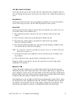
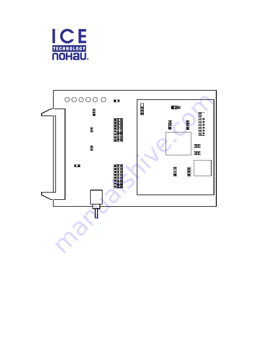
Figure 1. POD–51EH–C541U–12

Operating Instructions

The POD–51EH–C541U–12 supports the Siemens C541U controller which is based on the
C500 core.

This pod is supported by the 

EMUL51–PC

 Windows software version 2.1M or later. To work

with this pod, you need to choose processor C541U in the Hardware Configuration window.

The 

EPROM

 on the emulator board must be version 

COM

 1.4 or later. If it is an older version,

you need to replace it with a newer 

EPROM

.

Summary of Contents for POD-51EH-C541U-12

Page 1: ...RST P1 P3 7 6 5 4 3 2 1 0 USB FULL 3 2 1 D P D M Figure 1 POD 51EH C541U 12 Operating Instructions The POD 51EH C541U 12 supports the Siemens C541U controller which is based on the C500 core This pod...

Page 2: ...igh selecting single chip mode that is implemented by a 22K pull up resistor on the pin POD 51EH C541U 12 has two operating modes Single chip Expanded The active mode is selected by the EA pin during...

Page 3: ...d mode the jumper top needs to be across pins 2 and 3 This jumper is off by de fault DP DM Connection of the Emulator USB Plug When the DP and DM jumpers are on the D and D USB data line of the contro...

Page 4: ...STOP mode only The break mode needs to be se lected only if your application has limitations that do not allow the timers to be stopped in monitor mode XL0 XL7 Port Select Jumpers These eight 3 pin j...

Page 5: ...is important to feed the watchdog periodically otherwise problems during the debug process might occur 5 During hardware power down initiated by a low level detected on pin 69 HWPD of the target adap...

Page 6: ...is active when the user program is running Pins 2 and 3 are not used currently but can be used in the future J2 P3 6 P3 7 This header carries the recreated signals P3 6 WR pin J2 1 and P3 7 RD pin J2...

Page 7: ...e of single chip mode when the target does not force this pin This difference must be taken into account if the target pin is tied to a pull down resistor A sufficiently low pull down 1 5K or lower is...

Page 8: ...mA while main taining valid TTL output logic levels Port2 pins also have pull up resistors of 22K which might be different from the controller internal pull ups Connecting the Pod to a Target System 1...

Reviews: