background image

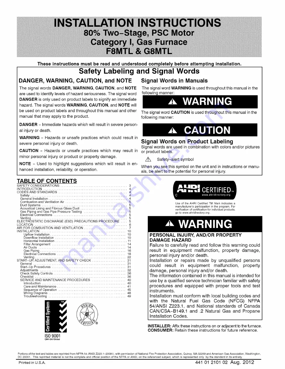
Summary of Contents for F8MTL

Page 1: ...ILATION 7 INSTALLATION 10 Upflow Installation 10 Downflow Installation 10 Horizontal Installation 11 Filter Arrangement 14 Air Ducts 14 Gas Piping 16 Electrical Connections 18 Venting 22 START UP ADJU...

Page 2: ...in 368 x 495 mm rectangle c For 1600 CFM 22 in 559 mm round or 14 1 2 x 22 1 16 in 368 x 560mm rectangle d For airflow requirements above 1800 CFM see Air Delivery table in Product Data literature fo...

Page 3: ...tion reliability or operation product and property damage NOTE is used to highlight suggestions which will result in enhanced installation reliability or operation 1 Use only with type of gas approved...

Page 4: ...ons that can result from inadequate combustion air supply or blocked vent conditions 1 Do not bypass limit switches 2 If a limit opens call a quallified serviceman to correct the condition and reset l...

Page 5: ...bjects and recharge your body with static electricity firmly touch a clean unpainted metal surface of the furnace again before touching control or wires 5 Use this procedure for installed and uninstat...

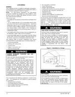
Page 6: ...ning solvents salts air fresheners and other household products Do not install furnace in a corrosive or contaminated atmosphere Make sure all combustion and circulating air requirements are met in ad...

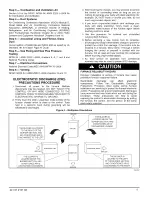
Page 7: ...of either unit unless the damper is in the full heat or full cool position AIR FOR COMBUSTION AND VENTILATION Provisions for adequate combustion ventilation and dilution air must be provided in accor...

Page 8: ...or Opening vent Figure 7 Air for Combustion Ventilation and Dilution for Outdoors 1 SQ IN DUCT PER 4000 TO BTUH OUTDOORS 305mm 12 MAX 1 SQIN A PER 2000 BTUH DUCTS TO OUTDOORS 1 SQ IN PER 2000 BTUH 30...

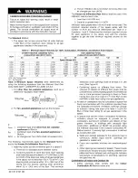
Page 9: ...hrJ A04003 combined input of all other than fan assisted appliances in Btuh hr combined input of all fan assisted appliances in Btuh hr air changes per hour ACH shall not exceed 0 60 The following re...

Page 10: ...n resistant machine bolts washers and nuts NOTE Bottom closure must be used when leveling legs are used It may be necessary to remove and reinstall bottom closure panel to install leveling legs To rem...

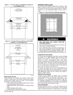
Page 11: ...ps plumber s straps may be used to suspend the furnace from each bottom corner To prevent screws from pulling out use two 2 8 x 3 4 in 19 mm screw into the side and 2 8 x 3 4 in 19 mm screw in the bot...

Page 12: ...e not required Downflow Applications on Noncombustible Flooring subbase not required Downflow Applications on Combustible Flooring subbase required Downflow Applications on Combustible Flooring with C...

Page 13: ...CK WASHERS REQ PER ROD Figure 16 Horizontal Suspension with Straps 22 GAUGE GALVANIZED STRAPS TYPICAL FOR 4 STRAPS A10130 OUTER DOOR F ASSEMBLY X III I IIII AIR OPENING METHOD 2 USE 4 8 x 3 4 19 ram S...

Page 14: ...utside the space containing the furnace Secure ductwork with proper fasteners for type of ductwork used Seal supply and return duct connections to furnace with code approved tape or duct sealer A10164...

Page 15: ...25 1765 1710 1650 1570 1475 1370 1240 1100 Low 1640 1620 1580 1540 1485 1410 1330 1220 1080 960 accessoryfilter A filter is required for each return air inlet Airflow performance included 3 4 in 19 mm...

Page 16: ...ations and Restrictions RETURN i AIR UPFLOW RETURN AiR CONFiGURATiONS AND RESTRICTIONS AIR FLOW MODELS RETURN AIR RETURN AIR RETURN AIR RETURN AIR CONNECTION 1 CONNECTION 2 CONNECTION 3 COMBINATIONS O...

Page 17: ...ed 36 inches 915 mm 3 When lever handle type manual equipment shutoff valves are used they shall be T handle valves 4 The use of copper tubing for gas piping is NOT approved by the state of Massachuse...

Page 18: ...ping should be pressure and leak tested in accordance with NFGC in the United States local and national plumbing and gas codes before the furnace has been connected After all connections have been mad...

Page 19: ...perates satisfactorily Unit ampacity 125 of largest operating component s full load amps plus 100 of all other potential operating components EAC humidifier etc full load amps 1 Time delay type is rec...

Page 20: ...green ground screw 12 Complete electrical box wiring and installation Connect line voltage leads as shown in Figure 23 Use best practices NEC in U S for wire bushings strain relief etc 13 Reinstall co...

Page 21: ...NOTE4 F_q F_q E3 E25 Fq D HUM 24VAC OUTDOOR SENSOR See notes 1 3 4 and 5 I Figure 28 Two Stage Furnace with Single Stage Heat Pump Dual Fuel ICP THERMOSTAT TWO STAGE SINGLE STAGE FURNACE HEAT PUMP F_...

Page 22: ...n and setup procedure 2 Outdoor Air Temperature Sensor must be attached in all dual fuel application 3 Refer to ICP thermostat Installation Instructions for additional information and setup procedure...

Page 23: ...t furnace control HUM 24VAC terminal to H humidifier terminal on humidity sensing thermostat or similar device See humidity sensing thermostat thermostat or controller manufacturer s instructions for...

Page 24: ...d for common venting and multi story venting with other fan assisted or draft hood equipped appliances in accordance with the NFCG local building codes and furnace and vent manufacturers instructions...

Page 25: ...ctions gaps No Condensate at bottom No Chimney exposed to outdoors below roof line No Yes _Not Suitable _LNo _ instructions for A _ b _ _ application _ _ _ _ _L _ _ Line chimney with property Suitable...

Page 26: ...rebuilt or relined to conform to the requirements of the equipment being installed and the authority having jurisdiction A chimney without a clay tile liner which is otherwise in good condition shall...

Page 27: ...d corrosion in the furnace and or venting system Derating is permitted only for altitudes above 2000 ft 3 Adjust the air temperature rise to the midpoint of the rise range or slightly above Low air te...

Page 28: ...lbow Left then Up SEE NOTES 1 2 4 5 6 7 8 9 10 on the page following these figures A03210 Figure 38 Downflow Application Vent Elbow Up ix SEE NOTES 1 2 4 5 7 8 9 on the page following these figures A0...

Page 29: ......

Page 30: ......

Page 31: ......

Page 32: ......

Page 33: ......

Page 34: ......

Page 35: ......

Page 36: ......

Page 37: ......

Page 38: ......

Page 39: ......

Page 40: ......

Page 41: ......

Page 42: ......

Page 43: ......

Page 44: ......

Page 45: ...a commercially available soap solution made specifically for the detection of leaks to check all connections Step 3 m Sequence of Operation NOTE Furnace control must be grounded for proper operation...

Page 46: ...ng as the BLWM is energized f Switching from Low to High Heat If the furnace control CPU switches from low heat to high heat the furnace control CPU will switch the inducer motor IDM speed from low to...

Page 47: ...blower motor BLWM will operate on continuous blower speed LO HEAT speed Terminal EAC 1 AMP is energized as long as the blower motor BLWM is energized During a call for heat the blower BLWM will stop...

Page 48: ...R OVERLOAD TEMPERATURE SWITCH N C PRINTED CIRCUIT BOARD CONTROL WHEN USED WHEN USED HI _ _ P4 v _rrl i _RED_ RED PB RED BW 12 CIRCUIT PCB CONNECTOR 3 CIRCUIT PCB HSI IDM CONNECTOR 3 CIRCUIT IDM CONNEC...

Page 49: ...connect the TEST TWIN terminal to the C thermostat fermi nal with a jumper wire to begin status code recovery and component test If a previous status code is present the code will repeat 4 times then...

Page 50: ...NOT CLOSE OR REOPENED Check for Control relay may be defective Gas valve is miswired Refer to status code 3 POLARITY Check for correct line voltage polarity If units are twinned check for proper low v...

Page 51: ...241 2 08 800 CFM 12 1200 CFM 14 1400 CFM 16 1600 CFM 20 2000 CFM 22 2200 CFM 1 2 3 F 8 M EFFICIENCY POSITION 4 5 T L TYPE FEATURE 6 7 8 045 HEAT INPUT 9 10 14 CABINET WIDTH 11 12 12 13 A 14 1 COOLING...

Reviews: