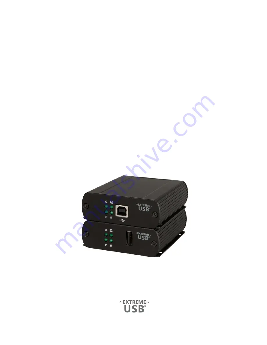
background image

USB 2.0 RG2301 Series

1-Port USB 2.0 CAT 5e/6/7 and Gigabit Ethernet LAN 

Extender Systems

User Guide

Summary of Contents for USB 2.0 RG2301

Page 1: ...USB 2 0 RG2301 Series 1 Port USB 2 0 CAT 5e 6 7 and Gigabit Ethernet LAN Extender Systems User Guide ...

Page 2: ...pt any interference received including interference that may cause undesired operation CE Statement We Icron Technologies Corporation declare under our sole responsibility that the USB 2 0 RG2301 Series to which this declaration relates is in conformity with European Standard EN 55022 EN 61000 and EN 55024 IC Statement This Class B digital apparatus complies with Canadian ICES 003 WEEE Statement T...

Page 3: ...01GE LAN models only 8 Requirements 8 Preparing Your Network 8 Preparing Your Site 9 Installing the Local Extender 9 Installing the Remote Extender 9 Checking the Installation 10 Connecting a USB Device 11 Pairing the Local Remote Extender RG2301N 2301S 2301GE LAN models only 11 Unpairing an Extender 11 Compatibility 11 Optional USB Extender Mounting Options 12 Option 1 USB Extender Mounting Kit 1...

Page 4: ...ps in bulk only not as a kitted system Features The RG2301 Series incorporates ExtremeUSB technology enabling users to extend USB beyond the standard 5m cable limit for USB 2 0 peripheral devices The RG2301 Series extender system is composed of two individual units the Local Extender and the Remote Extender and has the following key features 100m of extension when directly connected over CAT 5e 6 ...

Page 5: ...ders LED is slow blinking when the unit is attempting to establish a link LED is fast blinking to indicate the unit is in Pairing Mode 3 Host LED Green Indicates that the extender system is properly enumerated on the host computer LED blinks when the extender system is in a suspended state 4 Activity LED Green Indicates data transmission is occurring between local and remote extenders LED blinks i...

Page 6: ...e is no link between local and remote extenders LED is slow blinking when the unit is attempting to establish a link LED is fast blinking to indicate the unit is in Pairing Mode 3 Host LED Green Indicates that the extender system is properly enumerated on the host computer LED blinks when the extender system is in a suspended state 4 Activity LED Green Indicates data transmission is occurring betw...

Page 7: ...ices and or computer accordingly 3 If you are using surface cabling install the CAT 5e 6 7 cabling as desired and terminate it with the appropriate RJ45 ends 4 If using premise cabling in building network infrastructure ensure your cabling does not exceed 100m and that it meets CAT 5e 6 7 specification Cable installation is important particularly if high throughput applications are used When insta...

Page 8: ...er With Premise Cabling 1 Connect a CAT 5e 6 7 patch cable not provided into the information outlet near the host computer 2 Connect the patch cable into the Link port of the local extender 3 Connect a CAT 5e 6 7 patch cable not provided into the information outlet near the USB devices 4 Connect the patch cable into the Link port of the remote extender Installing the Remote Extender 1 Place the re...

Page 9: ...ay be configured to block devices with unfamiliar MAC addresses If this is the case you will need to provide your network administrator the MAC addresses of the local and remote extender units These can be found on the label on the bottom of each unit Some networks may be configured to block devices that consume a consistently high level of bandwidth The RG2301N 2301S 2301GE LAN may exhibit this b...

Page 10: ...ed USB cable between the local extender host port and a USB port on the host computer 3 Connect a CAT 5e 6 7 patch cable not provided into the information outlet near the host computer and then connect the patch cable into the Link port of the local extender Installing the Remote Extender 1 Place the remote extender near the USB device s 2 Assemble the power adapter and country specific power cord...

Page 11: ...sign If the extender system has been installed correctly you should find it listed as a Generic USB Hub To open Device Manager in Windows XP Right click My Computer then select Properties Hardware tab Device Manager To open Device Manager in Windows 7 Open the Start Menu right click on Computer then select Manage Device Manager To open Device Manager in Windows 8 8 1 or 10 Right click the Start Me...

Page 12: ...ll start flashing Pairing mode has been activated on the local extender 3 Within 10 minutes of activating the pairing mode on the local extender press and hold the Mode button on the bottom of the remote extender Release the button within 10 seconds The Link LED will start flashing Pairing mode has been activated on the remote extender 4 The Link LED on both units may start flashing more slowly be...

Page 13: ...urface Mounting 3 USB Extender Cable Tie Mounting Option 1 USB Extender Mounting Kit Order Part 10 00536 USB Mounting Kit 2301 12 Black Available for purchase separately 1 kit required to mount per Local Extender or Remote Extender Each kit includes 2 mounting brackets 4 M2 5 locking washers 4 M2 5 x 7 0mm Phillips pan head screws Mounting bracket installation guide see diagram below Using a Phill...

Page 14: ...surface 3 Drill through each of the four hole markings on the mounting surface using a 3 70mm 0 1457 drill bit 4 Align the bottom enclosure holes to the newly drilled out holes on the mounting surface 5 Place a locking washer on each of the four screws and using a screwdriver fasten the extender into place To ensure the stencil below prints to scale be sure to set the page scaling setting to none ...

Page 15: ...al and the remote extenders are off There is no connection between the local and remote extenders 1 Ensure CAT 5e 6 7 cable is connected between the local and remote extender units cable should be UTP or STP with a straight through connector and no crossovers and 8 conductor RJ45 connectors are used at both ends 2 Connect a short CAT 5e 6 7 patch cord between the local and remote extenders to dete...

Page 16: ...l extender from the computer 3 Disconnect the remote extender from the AC power adapter 4 Reconnect the local extender to the computer 5 Reconnect the remote extender to the AC power adapter 6 In the Universal Serial Bus controllers section of Device Manager check that the extender system is recognized as a Generic USB Hub My USB device does not work properly Insufficient bandwidth is available on...

Page 17: ...g information Host computer make and mode Type of operating system installed e g Windows 8 1 Windows 10 OS X 10 11 etc Part number and serial number of both the Local Extender and Remote Extender unit Make and model of any USB device s attached to this extender system Description of the installation such as Host computer model transmission media used and information about the USB device s Descript...

Page 18: ...face is what connects the network cabling CAT 5e 6 7 to the Local Extender unit and Remote Extender unit You may use either the T568A scheme Table 1 or the T568B scheme Table 2 for cable termination as the RG2301 Series requires all four pairs of the cable RJ45 connectors are sometimes also referred to as 8P8C connectors Note that any given cable must be terminated using the same T568 scheme on bo...

Page 19: ...5 Dimensions 86 0mm x 75 0mm x 26 0mm 3 4 x 3 0 x 1 0 Enclosure Material Black Anodized Aluminum REMOTE EXTENDER USB Connector 1 x USB 2 0 Type A Receptacle Link Connector 1 x RJ45 Dimensions 86 0mm x 75 0mm x 26 0mm 3 4 x 3 0 x 1 0 Enclosure Material Black Anodized Aluminum Available Current Up to 1 Amp Power Supply 100 240V AC input 5V 3A DC Output ENVIRONMENTAL Operating Temperature Range 0 C t...

Reviews: