background image

603GC Gas Utility Saw

Shop Manual

Summary of Contents for 603GC

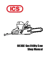
Page 1: ...603GC Gas Utility Saw Shop Manual...
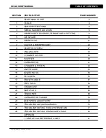
Page 2: ......

Page 3: ...LUTCH RIM SPROCKET 23 8 STARTER SYSTEM 27 9 WALLWALKER 33 10 CYLINDER COVER 35 11 MUFFLER 39 12 CARBURETOR 41 13 CYLINDER PISTON 43 14 WATER HOSE 52 15 IGNITION COIL 53 16 FLYWHEEL 55 17 FRONT HANDLE...

Page 4: ...arate parts attached solidly to each other Mark mating parts as a reassembly reference Keep component parts together as a group Assemble screws and nuts into appropriate subgroups When reassembling cl...

Page 5: ...4 71543 CYLINDER ASSEMBLY CLAMPS PISTON STOP 5 73462 MAIN BEARING DRIVER TOOL 6 71546 SHOCK ABSORBER TOOL 7 71547 SPARK TESTER 8 71548 FLYWHEEL PULLER TOOL 9 71550 LIMITER CAP REMOVAL TOOL 10 71565 E...

Page 6: ...retor Walbro diaphragm HDA 225 Air Filtration Canister polyester Starter Dust and water shielded Ignition Electronic speed governing water sealed Clutch Three weight single spring centrifugal Fuel Mix...

Page 7: ...Copyright May 24 2006 ICS Blount Inc 3 SERIAL LOCATION 3 603GC Cut Off serial number series 603GC SHOP MANUAL...

Page 8: ...lated to the key numbers in the 603GC Replacement Parts Price List KEY DESCRIPTION TORQUE LOCTITE PART NUMBER Nm in lbs 242 6 WRIST PIN NEEDLE BEARING 505403 11 CYLINDER BLOCK BOLT WASHER 1 1 95 X 738...

Page 9: ...CASE DOWEL PIN 73281 4 CHOKE LEVER 505409 5 BAR MOUNTING STUD 509555 6 CRANKCASE GROMMET 505408 7 WASHER 73897 9 BAR MOUNT PAD COVER PLATE 505467 12 CRANKCASE GASKET 505440 13 CHOKE LEVER BUSHING 7395...

Page 10: ...EEDLE BEARING 505403 7 CRANKSHAFT ASSEMBLY 505397 KEY DESCRIPTION TORQUE LOCTITE PART NUMBER Nm in lbs 242 8 CLUTCH SPRING 505434 10 CRANKCASE SEAL RETAINER 505423 11 CRANKSHAFT SEAL 505381 14 CLUTCH...

Page 11: ...ART NUMBER Nm in lbs 242 1 MUFFLER SUPPORT BRACKET SCREW 0 9 78 X 73885 2 SERRATED WASHER 73327 3 MUFFLER SUPPORT BRACKET 505392 4 MUFFLER MOUNTING SCREW 1 0 87 73883 5 SCREW 0 4 35 71482 6 WASHER 738...

Page 12: ...KE MANIFOLD 505383 21 CARBURETOR PULSE TUBE 73898 32 CARBURETOR SPRING 73888 36 WASHER 73897 38 CARBURETOR ATTACHMENT SCREW 0 5 43 X 73902 49 OUTER INTAKE MANIFOLD FLANGE SCREW 0 4 35 X 73901 54 CARBU...

Page 13: ...9 78 X 73982 10 WASHER 73897 11 FRONT HANDLE BOLT 0 8 69 X 73983 12 FRONT HANDLE 505424 13 FUEL FILTER 73459 14 FUEL LINE 73375 15 FUEL CAP O RING 73448 16 TRIGGER LOCKOUT LEVER 73987 17 TRIGGER LOCK...

Page 14: ...lount Inc 4 SPARE PARTS DIAGRAM KEY DESCRIPTION TORQUE LOCTITE PART NUMBER Nm in lbs 242 31 FLYWHEEL SHROUD 505438 45 FLYWHEEL 505399 48 NUT 3 0 260 73891 51 WAVE WASHER 73911 57 PLAIN WASHER 73912 71...

Page 15: ...ER 4 5mm 73285 40 SPARK PLUG CAP SPRING KIT 73241 41 SPARK PLUG SPRING 73917 43 IGNITION TOGGLE CABLE 73919 44 IGNITION COIL 505426 47 SWITCH IGNITION TOGGLE 73237 53 SCREW 0 7 61 X 73914 56 PLAIN WAS...

Page 16: ...TARTER ROPE HANDLE 505514 27 STARTER ROPE 508854 30 STARTER PULLEY SCREW 0 6 52 X 73907 34 RECOIL HOUSING SCREW 505380 35 STARTER PULLEY WASHER 73905 37 STARTER ROPE PULLEY 508857 42 STARTER ASSEMBLY...

Page 17: ...992 5 FILTER SUPPORT 73338 6 FILTER COVER GASKET 71756 7 CYLINDER COVER SCREW 0 5 43 X 505429 8 PREFILTER PLASTIC SECONDARY FILTER 73336 9 AIR FILTER FLANGE 71758 10 FILTER SUPPORT SCREW 0 3 26 X 5054...

Page 18: ...MBER Nm in lbs 242 1 HOSE CLAMP 71465 2 WATER HOSE 509488 3 WATER HOSE COVER 71464 4 HOSE HANGER 71461 5 WATER SHUT OFF VALVE 71458 6 WATER HOSE O RING 71468 7 RING NUT 71457 8 FITTING 71467 19 WATER...

Page 19: ...05468 12 SCREW 0 5 43 73982 13 GUARD FLAP MOUNTING BRACKET BACK 505490 14 GUARD FLAP MOUNTING BRACKET FRONT 505491 15 GUARD FLAP SCREW 71479 16 GUARD FLAP 505492 17 RUBBER BUMPER COVER 73310 18 SCREW...

Page 20: ...NUAL 18 Copyright May 24 2006 ICS Blount Inc 4 SPARE PARTS DIAGRAM KEY DESCRIPTION TORQUE LOCTITE PART NUMBER Nm in lbs 242 ABOVE CARBURETOR WALBRO HDA 225 517742 CARBURETOR REPAIR KIT 505441 CARBURET...

Page 21: ...nd assembly air induction system 5 1 Loosen the air filter cover screws and remove air filter cover 5 2 Remove air filter from cover A Inspect air filter B Replace if necessary P N 71752 5 3 Remove se...

Page 22: ...06 ICS Blount Inc 5 AIR INTAKE 5 4 Inspect air filter cover gasket A Replace if permanently depressed or hard due to slurry 5 5 Inspect filter cannister gasket A Clean B Replace if necessary 5 6 Secur...

Page 23: ...on and installation of the spark plug 6 1 Remove the spark boot taking care not to pry or damage the wire 6 2 Clean area around the spark plug to prevent debris from entering the cylinder 6 3 Remove t...

Page 24: ...nc 6 SPARK PLUG B Gap if necessary to 0 02 0 5 mm NOTE If the spark plug must be replaced refer to the Spark Plug Reference Guide on page 81 to select the correct replacement plug 6 5 Assemble in the...

Page 25: ...procket removal inspection and assembly Refer to sections 5 and 6 if needed 7 1 Insert piston stop tool into spark plug hole 7 2 Pull starter handle until piston stops against tool 7 3 Remove clutch L...

Page 26: ...Copyright May 24 2006 ICS Blount Inc 7 CLUTCH RIM SPROCKET 7 4 Remove all drive components 7 5 Inspect the clutch shoes for wear A Replace if the shoe has less than 0 04 1 mm of material as shown 7 6...

Page 27: ...HOP MANUAL 25 7 CLUTCH RIM SPROCKET 7 7 Assemble clutch A Insert top edge of clutch shoe over spring as shown B Snap clutch shoe into place 7 9 Inspect the rim sprocket for wear A Replace if the rim s...

Page 28: ...CKET 7 10 Clean and assemble A Clean all parts in solvent B Grease clutch cup bearing with a water proof grease ICS P N 70885 C Assemble clutch spacer washer bearing clutch cup with rim sprocket and i...

Page 29: ...nt of the recoil spring 8 1 Remove starter cover screws 8 2 Remove starter cover assembly from saw 8 3 Remove starter cord shield screws 8 4 Relieve spring tension A Pull 4 6 10 15 cm of rope out B Li...

Page 30: ...ley A Remove pulley screw 8 7 Inspect coil spring A Replace if spring hook is damaged Attempting to re bend the spring hook may cause the hook to break off B Carefully remove coil spring and housing t...

Page 31: ...all starter rope and tie knot 8 12 Knot tying instructions A Make a loop at the end of the pulley rope with the end of the rope crossing on top of the tail B Bring the end of the rope through the loop...

Page 32: ...eaving 4 6 out B Make sure that the pulley spring catch is in the spring hook 8 14 Install center screw A Use Loctite 242 B Torque to 26 in lbs 2 9 Nm 8 15 Wind the recoil spring A Line rope up with n...

Page 33: ...pawl components A Inspect the components Replace if necessary B Clean the components with a brush and solvent 8 19 Assemble components A Make sure the spring is in the correct position B Use Loctite 2...

Page 34: ...TITLE 603GC SHOP MANUAL 32 Copyright May 24 2006 ICS Blount Inc 8 STARTER 8 21 Install starter cover screws A Use Loctite 242 B Torque to 60 in lbs 7 Nm...

Page 35: ...L 33 9 WALLWALKER 9 This section covers the removal inspection and assembly of the rubber padded wallwalker and guard flap 9 1 Inspect bumpers A Replace if worn 9 2 Remove side cover assembly 9 3 Remo...

Page 36: ...ALLWALKER 9 5 Remove and inspect guard flap A Replace the flap if it is torn or damaged in any way 9 6 Remove guard flap screws and washers 9 7 Reassemble in the reverse order A Install crankcase scre...

Page 37: ...crews NOTE May require heat to remove screws 10 2 Remove the cylinder cover screws 3 10 3 Remove spark plug boot from cylinder cover taking care not to pry or damage the wire 10 4 Remove fuel tank bre...

Page 38: ...2006 ICS Blount Inc 10 CYLINDER COVER 10 7 Remove stop switch leads 10 8 Inspect cylinder cover for damage A Replace if necessary 10 9 Check filter cover gasket A Replace if necessary 10 10 Check cyli...

Page 39: ...boot is in place 10 13 Install cylinder cover A Pull spark plug lead into slot in cylinder cover B Lubricate compensating tube 1 and fuel tank breather tube 2 with soapy water guide through cylinder c...

Page 40: ...tite 242 Torque to 35 in lbs 4 0 Nm 10 14 Install air filter mount A Guide carburetor compensating tube through air filter mount Make sure manifold sits flat over lip on cylinder cover B Install air f...

Page 41: ...muffler Removal of the bumpers and cylinder cover is necessary Refer to sections 9 and 10 if necessary 11 1 Remove muffler support screws 11 2 Remove muffler screws 2 note there are two screws and ser...

Page 42: ...screws in place with heat shield gasket C Thread muffler screws into cylinder torque to 78 in lbs 9 Nm 11 5 Install muffler support A Install top 3 muffler support screws and serrated washer finger ti...

Page 43: ...is covered in section 22 12 1 Remove throttle linkage A Push trigger end out of rear handle B Pivot linkage around C Remove carburetor end of linkage from throttle rod tab on carburetor NOTE All saws...

Page 44: ...ve carburetor A Remove pulse tube B Remove carburetor jet cover C Remove carburetor from choke linkage 12 5 Assemble in the reverse order A Torque carburetor body screws to 43 in lbs 5 Nm B Torque sup...

Page 45: ...ired Refer to sections 5 6 10 and 12 if necessary 13 1 Remove carburetor base screws A Remove carburetor base bracket from rear manifold B Remove carburetor base bracket from pulse tube 13 2 Remove pu...

Page 46: ...ICS Blount Inc 13 3 Remove rear manifold clamp 13 4 Remove rear manifold from cylinder A Inspect for holes and tears 13 5 Remove cylinder screws 4 and wave washers 13 6 Remove cylinder A Remove cylind...

Page 47: ...S Blount Inc 603GC SHOP MANUAL 45 13 7 Remove wrist pin retaining clips 2 13 8 Press wrist pin out with an 8 mm deep socket 13 9 Remove piston and inspect Replace if damaged 13 10 Remove wrist pin bea...

Page 48: ...le cylinder gasket A Oil gasket with ICS 2 stroke engine oil B Install and align holes and notch 13 12 Install wrist pin bearing in rod A Oil bearing with ICS 2 stroke engine oil 13 13 Install rings A...

Page 49: ...ing clip is in the proper orientation Improper installation may result in serious engine damage NOTE Never attempt to reuse wrist pin retaining clips or substitute wrist pins from another model or bra...

Page 50: ...rientation A Make sure arrow points to exhaust port 13 19 Install piston A Oil piston with ICS 2 stroke oil B Align wrist pin with wrist pin bearing C Complete wrist pin installation D Install second...

Page 51: ...h ring compression tool C Slide cylinder onto piston pushing ring compression tool down 13 21 Install cylinder A Remove ring compression tool B Slide cylinder down piston and into crankcase C Align cy...

Page 52: ...of intake boot with casting seams of the cylinder 13 24 Install rear manifold clamp A Torque to 11 in lbs 1 Nm NOTE Insure that the intake boot is properly installed DO NOT OVER TIGHTEN INTAKE BOOT CL...

Page 53: ...A Slip pulse tube into carburetor base B Slip rear manifold into carburetor base C Make sure rear manifold lip is flat 13 28 Install carburetor base screws A Use Loctite 242 on screws 3 B Make sure t...

Page 54: ...side cover 14 1 Inspect water hose and side cover A Replace if damaged 14 2 Assemble in reverse order 14 3 Remove water hose connector from side cover A Remove clamp and hose from fitting B Unthread...

Page 55: ...l of the starter is required Refer to section 8 if necessary 15 1 Remove starter flywheel shroud by unhooking wires 15 2 Remove ignition coil screws wave washers and plain washers 15 3 Remove ignition...

Page 56: ...nstall ignition coil screws wave washers and plain washers with Loctite 242 Holding shim rotate flywheel magnet around to coil E Torque ignition coil screws to 26 in lbs 3 Nm F Remove shim rotate flyw...

Page 57: ...flywheel Removal of spark plug and the starter is required Refer to sections 6 and 8 if necessary 16 1 Insert piston stop 16 2 Remove flywheel nut wave washer and plain washer 16 3 Screw on flywheel...

Page 58: ...val tool with a ball peen hammer The flywheel should release from crankshaft 16 6 Inspect and clean flywheel Replace if any of the fins are broken 16 7 Inspect cast woodruff key inside the flywheel NO...

Page 59: ...val inspection and installation of the front handle 17 1 Remove front handle screws on right side 17 2 Remove front handle screws on bottom 17 3 Install front handle A Roll front handle into place B I...

Page 60: ...covers the disassembly inspection and assembly of the vibration isolaters fuel tank and rear handle 18 1 Remove vibration isolator screws 2 and wave washers on clutch side of saw 18 2 Remove vibratio...

Page 61: ...l tank NOTE Saws have a rubber water deflector connected to the 2 bottom vibration isolators on the clutch side circled 18 4 Remove vibration isolators 4 from fuel tank if necessary 18 5 Assemble in r...

Page 62: ...2006 ICS Blount Inc 19 This section covers the disassembly inspection and assembly of the crankcase seals and crankshaft bearings 19 1 Remove outer crankshaft seal housing screws and wave washers 19 2...

Page 63: ...tes approximately 150 F 65 5 C 19 4 Remove the flywheel side crankcase tap crankshaft with plastic mallet A Suspend above work surface B Tap with mallet NOTE A nut should always be placed on a threade...

Page 64: ...ase Heat the clutch side crankcase with heat gun to 150 F 65 5 C 19 7 Remove crankshaft from the clutch side crankcase tap crankshaft with a plastic mallet A Suspend above work surface B Tap with plas...

Page 65: ...emove the bearing seal and bushing from the clutch side of crankshaft 19 10 Assembly of crankcase A Clean mating crankcase faces 19 11 Heat crankcase halves to 150 F 19 12 Install bearing into crankca...

Page 66: ...yright May 24 2006 ICS Blount Inc 19 14 Repeat with other half 19 15 Install crankshaft into clutch side of case 19 16 Place clutch side crankcase seal on crankshaft A Tap lightly with bearing driver...

Page 67: ...Blount Inc 603GC SHOP MANUAL 65 19 17 Coat crankcase gasket with ICS 2 stroke engine oil 19 18 Align crankcase gasket on flywheel side crankcase pins 19 19 Place crankcase halves together and align cr...

Page 68: ...S Blount Inc 19 20 Assemble crankcase halves tap with bearing driver and mallet 19 21 Install crankcase bolts A Use Loctite 242 B Torque to 69 in lbs 8 Nm 19 22 Install flywheel side crankcase seal ta...

Page 69: ...ight May 24 2006 ICS Blount Inc 603GC SHOP MANUAL 67 19 23 Assemble in reverse order A Install outer crankshaft seal housing with 3 bolts and use Loctite 242 19 24 Trim crankcase gasket flush 19 CRANK...

Page 70: ...he bar studs and bar pad 20 1 On 603GC saws NOTE This requires the removal of the piston and cylinder and to split the crankcase Refer to section 13 19 for detailed instructions A Remove side cover B...

Page 71: ...the chain tensioner 21 1 Remove bar plate to expose the chain tensioner 21 2 Unscrew tensioner to remove A Remove tensioner pin B Remove tensioner screw keeper 21 3 Assemble in reverse order NOTE The...

Page 72: ...al to adjust carburetor to factory recommended settings DO NOT adjust the carburetor for maximum rpm Adjusting the carburetor for maximum rpm will cause engine damage Always set the carburetor jets to...

Page 73: ...e orientation of the release slots on the adjustment screw limiter cap B Insert the limiter cap puller blades into the release slots C Firmly hold the tool shaft while screwing in the puller screw unt...

Page 74: ...5 Start the saw and warm up the engine 22 6 With a tachometer check the saw rpm with bar and no chain A Idle 3 000 300 rpm B If the idle rpm does not fall into this range adjust the T screw clockwise...

Page 75: ...ay 24 2006 ICS Blount Inc 603GC SHOP MANUAL 73 22 9 When the carburetor is adjusted correctly set the limiter caps as shown with a 1 4 straight blade screwdriver A L vertical B H horizontal 22 CARBURE...

Page 76: ...ers idle speed adjustment 23 1 If engine stops while idling A Make sure the chain is properly tensioned B Turn T screw clockwise until chain begins to move C Back T screw out turn 23 2 If chain turns...

Page 77: ...high Broken clutch spring Excessive vibration YES Damaged shock absorber Damaged or broken flywheel fins Bent crankshaft Replace shock absorbers Replace flywheel Replace crankshaft Adjust idle speed R...

Page 78: ...is old varnished or contaminated Empty tank and re fill with fresh fuel of the correct mixture 25 1 Loose spark plug If below 125 psi excess wear on the piston cylinder rings Tighten plug and re test...

Page 79: ...e fuel tank fuel tank breather fuel filter delivery tubes and carburetor 25 1 Remove and inspect the fuel filter A Replace the fuel filter if there is any foreign material in the felt or the internal...

Page 80: ...hragm Carburetor Service Manual 25 3 The fuel tank breather stabilizes the pressure in the fuel tank preventing both excessive pressure which could flood the engine and negative pressure which could s...

Page 81: ...si disassemble or replace the breather A Disassemble by snapping off cap B Clean parts with solvent or fuel 25 7 Assemble in reverse order A Make sure duck bill opens easily B Make sure that the sprin...

Page 82: ...seal flange A Plug cylinder pulse tube 26 2 Install the exhaust seal flange 26 3 Block one of the flange tubes with a rubber plug 26 4 Install the pressure gauge and bulb 26 5 Pressurize the crankcas...

Page 83: ...g Reference Guide is to be used as a guide only When trying a plug from a different manufacturer perform a plug check to be sure that the plug will work SPARK PLUG REFERENCE GUIDE ICS RESISTOR CHAMPIO...

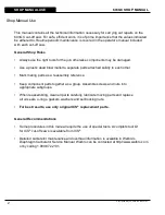
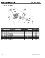
Page 84: ...603GC SHOP MANUAL 82 Copyright May 24 2006 ICS Blount Inc...

Page 85: ...Copyright May 24 2006 ICS Blount Inc ICS Blount Inc 4909 SE International Way Portland Oregon 97222 TEL 800 321 1240 FAX 503 653 4393 www icsbestway com p n 71537...

Reviews: