background image


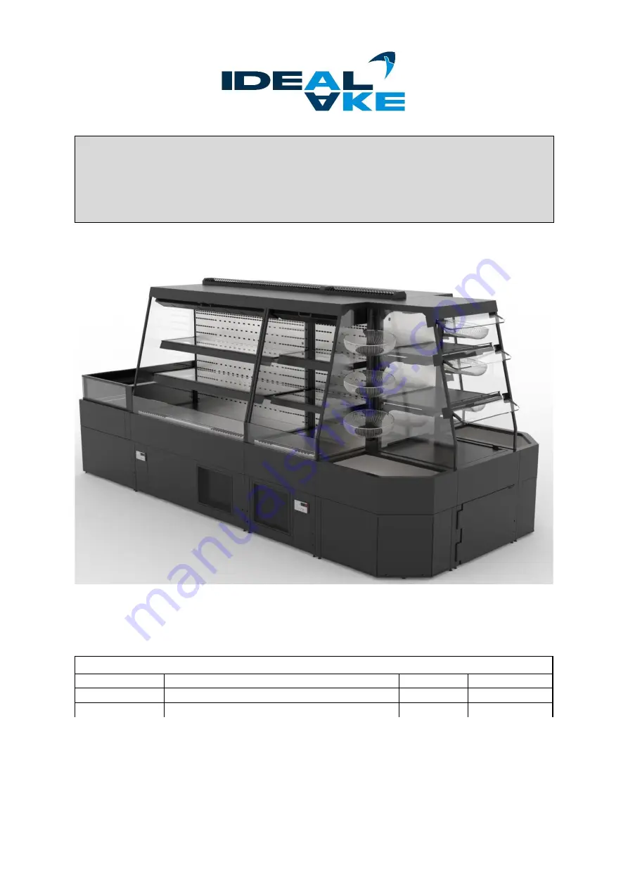
ASSEMBLING GUIDELINE  

Caleo System


Ausseer Kälte- und Edelstahltechnik GmbH


Document: 

MA_Caleo System_EN_21A 

valid: 

2021-01 

Document Nr. 

TD-AKE-00000855 

version: 

21A 

Note: 

Translated version from original document 

language: 

Englisch 

Copyright 2021 of AKE Ausseer Kälte- und Edelstahltechnik GmbH. 
The content of this publication may not be reproduced without  prior written consent of AKE GmbH  in 
whole or in part, be reproduced in any form, or to third parties. AKE GmbH reserves the right to make 
technical changes and modifications to these operating instructions without notice. 
All rights reserved. 

Summary of Contents for Caleo

Page 1: ...inal document language Englisch Copyright 2021 of AKE Ausseer Kälte und Edelstahltechnik GmbH The content of this publication may not be reproduced without prior written consent of AKE GmbH in whole or in part be reproduced in any form or to third parties AKE GmbH reserves the right to make technical changes and modifications to these operating instructions without notice All rights reserved ...

Page 2: ... back Side by side installation 4 2 3 Levelling of Caleo unit 6 3 cover plates panels 7 3 1 1 back panel cover plate 7 3 1 2 bottom well cover plate 8 3 1 3 air flow adapter 8 3 1 3 1 air duct cover panel 8 3 1 4 cover plate for double glass 9 3 1 5 side cover plate 9 3 1 6 waste air panel 9 3 1 7 front glass connector 10 4 Additional equipment 11 4 1 product basket 11 4 2 glass shelves 11 4 3 cor...

Page 3: ...for the content particularly for damages through existing non existing or incorrect details The passing on and amendment of this manual is not permitted if not expressly authorized by company AKE GmbH Before starting with the assembling installation please follow these instructions It is mandatory to carry out a safety related and procedural instruction with the employees technicians operators Che...

Page 4: ... the left front base frame tube on each unit Connect two units standing next to each other with a screw M8x20mm DIN912 to the provided blind rivet nut NOTE The base frame cover may have to be drilled A back panel connector must be attached to the upper corners of each back wall 2 2 Back to back Side by side installation Step 1 All Units must be levelled and adjusted on same height before build up ...

Page 5: ...th hexagon socket screws M6 or with special bolts as shown in the picture see chapter 3 1 6 using with air waste panel NOTE Check the tight fit of the mounting plates Step 5 Attach the side cover panel on the outermost left and right exposure of the system Assembling instructions steps see chapter 3 1 5 Step 6 Attach the waste air panel on the top of side cover panels Assembling instructions steps...

Page 6: ...the unit in total horizontal direction Tool needed hex tool 4mm NOTE Turn the adjusting screw clockwise for lifting or counter clockwise for lowering Frontside adjustment feet of unit Backside adjustment feet of unit NOTE The adjustment of levelling can be done from frontside position with special tool or be done in the base frame remove the front cover of unit ...

Page 7: ...ell cover plate Cover plate double glass Side cover panel Air flow adapter waste air panel Front glass connector 3 1 1 back panel cover plate Install the cover on the backwall frame endings between two units Assembly specification Installed on unit Top view back panel cover bottom view back panel cover NOTE The notch must be hooked into the sheet metal edges air flow adapter bottom well cover plat...

Page 8: ...duct cover panels Install the air flow adapter between cooling units Assembly specification Installed on unit NOTE fix it with torx screws 6x torx M3x10mm the air duct cover panel must be dismantled 3 1 3 1 air duct cover panel All cooling units are produced and delivered in standard version with installed air duct cover panels When installing a cooling unit next to each other the cover panels mus...

Page 9: ...1 5 side cover plate Place the side cover plate on the back panel of a unit when build up back to back to each other or use them as a cover panel for stand alone devices Assembly specification Installed on unit Attach the cover on the backwall end and fix it with the locking screws NOTE Ensure that the closed side of the plate is installed facing to the outside direction 3 1 6 waste air panel Plac...

Page 10: ...tor fixes the front glass panels and is used when two units are installed next to each other The front glass connector is used by installing two units to each other Assembly specification Installed on unit NOTE Different glass connectors can be installed with or without using the side glasses in installed version ...

Page 11: ...ssembly specification Installed on unit NOTE Depending on the model device the mounting holes have to be drilled 4 2 glass shelves Depending on the design and structure glass shelves can be attached to the front sides of the system They are mounted to the side panels with glass shelf brackets The glass shelf brackets are fixed to the system sides with suitable screws Assembly specification Install...

Page 12: ...end Like all Caleo units are connected to each other it is attached by base frame Remove the front panel and fasten the corner module with a suitable screw M8 Remove front panel Base frame assembly connection NOTE After installation the corner module can be leveled using the adjustable foot 5 Built up sample View of Caleo System Cold View of Caleo System Hot ...

Reviews: