background image

Classic RS 330-360

Wall hung, balanced

flue, gas fired boilers

Summary of Contents for Classic RS 300

Page 1: ...Classic RS 330 360 Wall hung balanced flue gas fired boilers ...

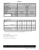
Page 2: ...ical supply 230 V 50 Hz Fuse rating External 3A Water content litre gal 3 65 0 8 4 6 1 0 Dry Weight kg lb 46 3 107 1 54 2 119 5 Maximum installation weight kg lb 34 7 76 5 42 7 94 2 Boiler size Height mm in 600 23 6 Width mm in 380 15 0 Depth mm in 300 11 3 4 Table 1 General Data Table 2 Performance Data CAUTION To avoid the possibility of injury during the installation servicing or cleaning of th...

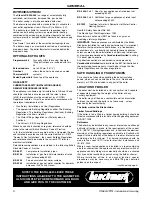
Page 3: ... 10 Classic RS 350 41 392 11 Classic RS 360 41 392 12 Natural Gas only I2H BENCHMARK LOG BOOK DETAILS Boiler Page Make and model 3 Appliance serial no on data badge 8 SEDBUK No 2 Controls Time and temperature control to heating 16 17 Time and temperature control to hot water 16 17 Heating zone valves 16 17 TRV s 7 Auto bypass 7 Boiler interlock 7 For all boilers Flushing to BS 7593 7 Inhibitor 7 C...

Page 4: ...ETE THE BENCHMARK LOG BOOK AND GIVE THIS TO THE CUSTOMER BS 5440 Part 1 Flues for gas appliances of rated input not exceeding 60 kW BS 5440 Part 2 Ventilation for gas appliances of rated input not exceeding 60 kW BS 7593 Treatment of water in Domestic Hot Water Central Heating Systems Health Safety Document No 635 The Electricity at Work Regulations 1989 Manufacturer s notes must NOT be taken in a...

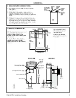
Page 5: ...structions supplied with the kit 3 If the boiler is to be used for gravity domestic hot water supply then cut off the spun ends of the gravity flow and return pipes and fit a 22 mm to 28 mm copper connection at the boiler gravity flow and return connections in order to run the gravity circuits in 28 mm pipe Front clearance 450mm 17 3 4 from the front of the boiler casing Minimum front clearance wh...

Page 6: ... Ltd Tower House Vale Rise Tonbridge Kent TN9 1TB Tel 44 0 1732 359 888 Fax 44 0 1732 354 445 www tfc group co uk Ensure that the guard is fitted centrally 5 If a natural draught terminal is fitted less than 1m below a plastic gutter or less than 0 5m below painted eaves or any other painted surface a suitable shield at least 1m long should be fitted to protect the surface 6 The air inlet products...

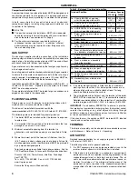
Page 7: ...instructions 2 If the boiler is installed in an existing system any unsuitable additives MUST be removed by thorough cleansing BS7593 1992 details the steps necessary to clean a domestic heating system 3 In hard water areas treatment to prevent limescale may be necessary however the use of artificially softened water is NOT permitted 4 Under no circumstances should the boiler be fired before the s...

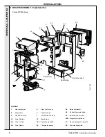
Page 8: ...ode 22 Thermostat pocket 25 Boiler thermostat 26 Control thermostat knob 34 Balanced flue terminal 44B Programmer optional 47 Gasket grommet bush kit 53 Wall mounting plate Data badge Programmer 34 4 2 5 4 3 4 1 47 34 53 26 6 2 3 7 1 22 25 18 1 12 Controls support Clas 1998 LEGEND 1 Heat exchanger 2 Flue baffles 3 Hook bolt kit assy 4 1 Pipe RH flow 4 2 Pipe LH flow 4 3 Pipe Return INSTALLATION ...

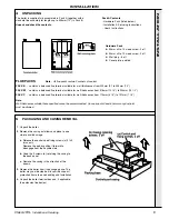
Page 9: ...of at least 50mm at any duct joint must be allowed Hardware Pack 50mm x No 14 wood screw 3 off 50mm x No 10 wood screw 3 off Wall plug 6 off Cover plate painted 5 PACKAGING AND CASING REMOVAL 1 Unpack the boiler 2 Remove the casing as follows and place to one side to avoid damage a Release the controls pod fixing screws a 3 full turns only Remove the pod by pulling it forward to disengage from the...

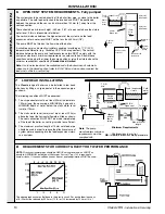
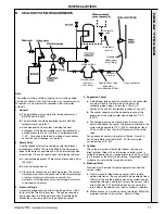
Page 10: ...requirements to avoid cavitation Should these conditions not apply either lower the pump position or raise the cistern above the minimum requirement specified by Caradon Ideal Limited Note A cold water feed must be available back to the boiler when all automatic valves are in the closed position refer to BS 6798 and when close coupled the feed must not be in a vertical leg System return Connection...

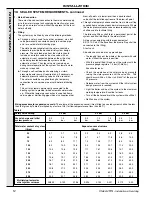
Page 11: ... Vessel a A diaphragm type expansion vessel must be connected at a point close to the inlet side of the pump the connecting pipe being not less than 15mm 1 2 nominal size and not incorporating valves of any sort b The vessel capacity must be adequate to accept the expansion of the system water when heated to 110 o C 230 o F c The charge pressure must not be less than the static water head above th...

Page 12: ... the stop valve being located between the system and the automatic air vent The stop valve may remain open during normal operation of the system if automatic water make up is required b Through a self contained unit comprising a cistern pressure booster pump if required and if necessary an automatic pressure reducing valve and flow restrictor The cistern should be supplied through a temporary conn...

Page 13: ...top cover plate screw holes 7mm 9 32 and insert the plastic plugs 4 Remove the template from the wall IMPORTANT The wall must be of suitable load bearing capacity 1 Cut the appropriate hole in the wall for insertion of the terminal assembly Note The terminal must not come into contact with a combustible material such as that used in the non standard construction of timber framework and plasterboar...

Page 14: ...he opposite end to the brackets and on the mating face of the boiler air duct use one sachet of sealant 3 Push the terminal air duct fully in until the fixing brackets contact the wall face 4 Make good between the wall and duct from OUTSIDE of the building 5 From OUTSIDE of the building pass the terminal flue duct through the wall opening and slide it over the boiler flue duct Locate it as shown 6...

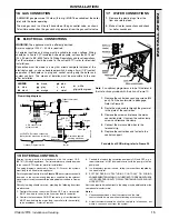
Page 15: ...should be in 3 core PVC insulated sheathed cable not less than 0 75mm2 24 x 0 2mm to BS 6500 Table 16 Wiring Regulations and local regulations For IE reference should be made to the current ETCI rules for electrical installations Connection must be made in a way that allows complete isolation of the electrical supply such as a double pole switch having a 3mm 1 8 contact separation in both poles or...

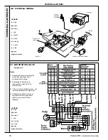
Page 16: ... Midi is similar in operation but the wiring differs slightly see manufacturer s literature 21 MID POSITION VALVE LEGEND b blue bk black br brown r red y yellow w white or orange v violet p pink gy grey y g yellow green 20 PICTORIAL WIRING bk br b y g y g y g gy br bk bk br b y g Overheat thermostat if fitted Printed ciruit board Clas 2110 Ignition detection electrode Gas valve MAINS b br y g r Pu...

Page 17: ...tinuity when wiring 2 Numbering of terminals on thermostats is specific to the manufacturer 3 This is a fully controlled system set the boiler thermostat to maximum 4 Switchmaster valve has grey and orange auxiliary switch leads but the grey wire must be connected to the live supply LEGEND b blue bk black br brown r red w white or orange y g yellow green gy grey Pumped only 23 HONEYWELL C PLAN LEG...

Page 18: ...ts as a storage heater and can normally be left at least 24 hrs without frost damage However if parts of the pipework run outside the house or if the boiler will be left off for more than a day or so then a frost stat should be wired into the system This is usually done at the programmer in which case the programme selector switches are set to Off and all other controls MUST be left in the running...

Page 19: ... gauge via a flexible tube 5 Swing the control box back into its working position 6 Switch the electricity supply ON and check that all external controls are calling for heat 7 Press the overheat thermostat reset button G if fitted 8 Set the boiler thermostat knob D to maximum The pilot gas valve should open and pilot ignition commence When the pilot is alight the main burner will cross light smoo...

Page 20: ...n of the boiler and the use and adjustment of ALL system controls should be fully explained to the Householder to ensure the greatest possible fuel economy consistent with household requirements of both heating and hot water consumption Advise the User of the precautions necessary to prevent damage to the system and to the building in the event of the system remaining inoperative during frosty con...

Page 21: ...ctly refitted ensuring that a good seal is made The boiler must NOT be operated if the casing is not fitted Note In order to carry out either servicing or replacement of components the boiler casing must be removed Frame 30 31 BURNER AND AIR BOX REMOVAL 1 Remove the screw retaining the burner support bracket to the combustion chamber 2 Remove the M5 pozi screw situated at the LH bottom rear of the...

Page 22: ...If after removing and checking the injector as detailed in Frame 43 and ensuring that there is an inlet pressure of 20 mbar available the pilot does not light then contact Caradon Ideal Limited Relight in accordance with Initial Lighting Frame 26 1 Brush off any deposits that may have fallen on to the burner head ensuring the flame ports are unobstructed and remove any debris that may have collect...

Page 23: ...that a good seal is made 37 SIGHTGLASS REPLACEMENT 36 GENERAL Note In order to assist fault finding the control box printed circuit board is fitted with 2 indicator lights which represent the following boiler conditions Neon I3 Mains electricity ON Neon SG1 Flashes to indicate ignition operation stops after detection The boiler MUST NOT be operated if the casing is not fitted 1 Refer to Frames 36 ...

Page 24: ...ield and electrode 4 Unscrew the central pilot fixing screw and lift the pilot burner clear of the pilot injector If required the pilot injector may now be unscrewed 5 Replace the pilot burner and injector if necessary and retain with the M4 screw previously removed Ensure that the copper sealing washer is replaced when refitting the pilot injector 40 PILOT BURNER REPLACEMENT 6 Replace the electro...

Page 25: ...he burner Pull the burner downward to disengage the retention tab and remove the burner 4 At this stage the main burner injector can be removed checked cleaned or replaced as required Ensure that an approved jointing compound is used sparingly 5 Fit the new burner ensuring that the retention tab is correctly located in the air box slot 6 Refit the M5 retaining screw 7 Refit the boiler casing 9 Che...

Page 26: ...approved jointing compound on the pipe stub 9 Reassemble in reverse order 10 Replace the boiler casing 11 Check the gas valve operation 46 COMBUSTION CHAMBER INSULATION REPLACEMENT 1 Refer to Frame 36 2 Remove the burner and air box assembly Refer to Frame 43 3 Remove the 4 tie rods 4 Remove the combustion chamber 5 Remove the 2 side panel retaining brackets 6 Remove the side insulation panels 7 R...

Page 27: ... the heat exchanger inter panel assembly upward and forward to disengage key hole fixings Pull the assembly downward to clear the water pipes from the back panel 10 Remove the 2 rubber sealing grommets from the top of the back panel to facilitate fitting the new assembly 11 Fit the new heat exchanger assembly complete with water pipes and hang it on the key hole slots and screws Retighten the scre...

Page 28: ...the overheat stat be reset when the system is cold NO YES NO Replace fuse BUT before attempting to start boiler check for short between live and neutral also between live and earth on all items plugged into the PCB Has the fuse blown on PCB Replace the overheat thermostat Check gap at ignition electrode Check electrode and lead are undamaged and not close to earthed metalwork NO NO YES NO YES Has ...

Page 29: ...ers Key No G C Part No Description Qty Product No 9 308 365 Sightglass assembly kit 1 171 414 12 Main burner RS 330 RS 340 1 171 013 Main burner RS 350 RS 360 1 171 416 13 Main burner injector RS 330 RS 340 1 171 425 Main burner injector RS 350 1 171 426 Main burner injector RS 360 1 171 427 14 397 943 Pilot burner injector 1 171 434 15 308 358 Pilot burner head with injector 1 171 438 17 Gas valv...

Page 30: ...30 Classic RS Installation Servicing SHORT LIST OF PARTS 50 SHORT PARTS Cla 2124 9 12 13 14 15 17 26 25 18 1 18 39 45 19 23 51 BOILER CASING ASSEMBLY 37 35 ...

Page 31: ... Burner manifold 11 Air box and pilot assembly 12 Main burner C l a s 2 1 2 3 Optional Extra 19 25 26 23 LEGEND 19 Control box 25 Boiler thermostat 23 Printed circuit board 26 Thermostat knob 52 CONTROL BOX Exploded View 13 Main burner injector 16 Pilot shield 17 Gas control valve 42 Gas service cock ...

Page 32: ...fication without notice The Ideal Boilers Technical Training Centre offers a series of first class training courses for domestic commercial and industrial heating installers engineers and system specifiers For details of courses please ring 01482 498 432 THIS SYMBOL IS YOUR ASSURANCE OF QUALITY These appliances are designed for use with Natural Gas only They have been tested and conform with the p...

Reviews: