background image

Warning: (1) Periodic inspection and maintenance of Corken products is essential. (2) Inspection, maintenance and installation of
Corken products must be made only by experienced, trained and qualified personnel. (3) Maintenance, use and installation of Corken
products must comply with Corken instructions, applicable laws and safety standards (such as NFPA Pamphlet 58 for LP-Gas and
ANSI K61.1-1972 for Anhydrous Ammonia). (4) Transfer of toxic, dangerous, flammable or explosive substances using Corken products
is at user’s risk and equipment should be operated only by qualified personnel according to applicable laws and safety standards.

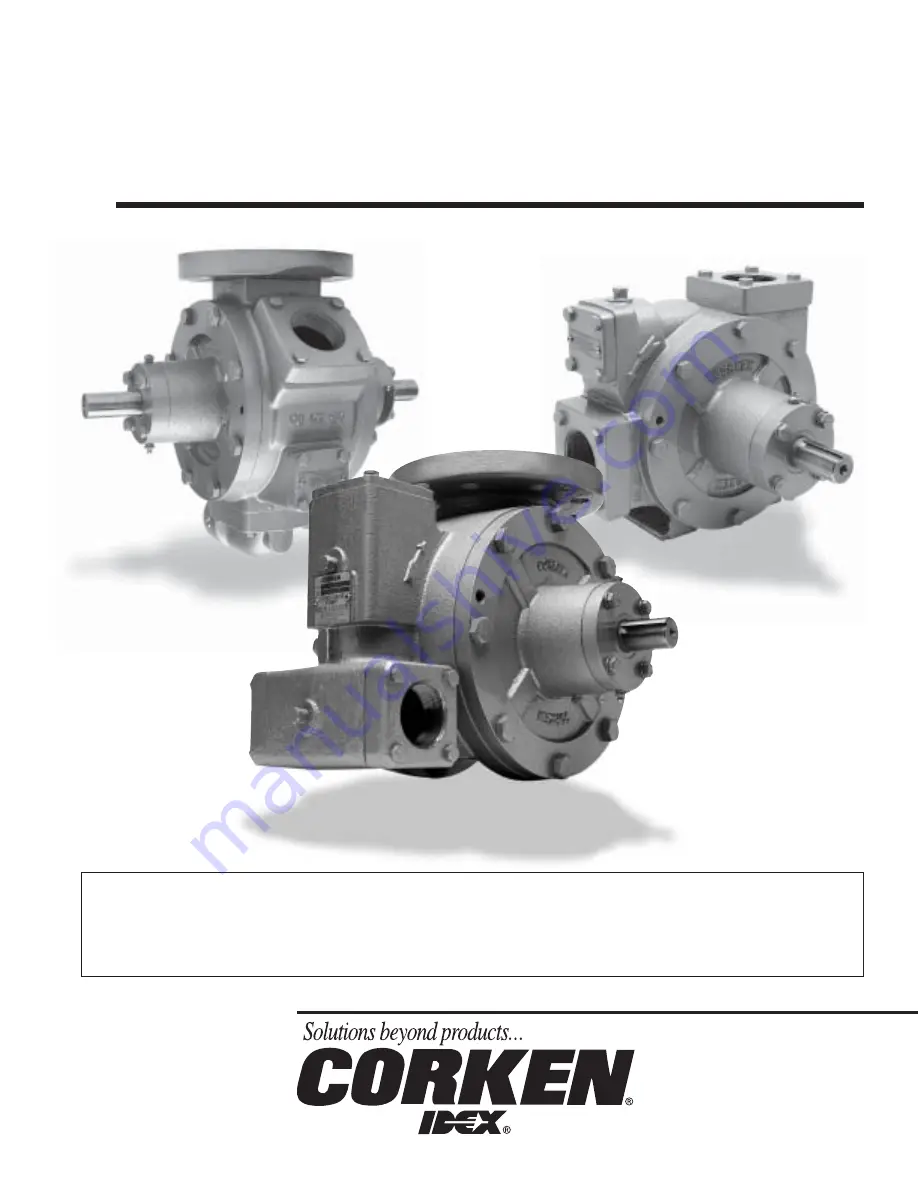
Installation, Operation

& Maintenance Manual

Z-Series Truck Pumps

Z3200

ID105E

Z2000

Z4200

Summary of Contents for Corken Z-Series

Page 1: ...ts must comply with Corken instructions applicable laws and safety standards such as NFPA Pamphlet 58 for LP Gas and ANSI K61 1 1972 for Anhydrous Ammonia 4 Transfer of toxic dangerous flammable or explosive substances using Corken products is at user s risk and equipment should be operated only by qualified personnel according to applicable laws and safety standards Installation Operation Mainten...

Page 2: ... at the user s risk Such substances should be handled by experienced trained personnel in compliance with governmental and industrial safety standards Important notes relating to the European Union EU Machinery Directive Pumps delivered without electric motors are not considered as machines in the EU Machinery Directive These pumps will be delivered with a Declaration of Incorporation The fabricat...

Page 3: ...pacity 6 Maintenance of Your Z Series Coro Vane Truck Pump System 7 Pump Maintenance Schedule 7 Preventive Maintenance Program 8 Z Series Coro Vane Seal Replacement Instructions 9 Repair Re build Kits 11 Assembly Instructions For Z Series Truck Pumps 12 Parts Details 13 Appendix A Model Number and Identification Code 16 Appendix B Operating Material and Flange Specifications 17 Appendix C Performa...

Page 4: ... 1 4 pipethread areprovided The RELIEF VALVE is built in and nonadjustable The valve is preset at the factory NOTE EVEN WITH THIS INTERNAL SAFETY VALVE AN EXTERNAL BY PASS VALVE MUST BE INSTALLED Installation of Your Corken Z Series Coro Vane Pump The installation of the Z Series CORO VANE pump is simple However in order for the pump to deliver optimum performance the principles discussed in this ...

Page 5: ...edinthedischarge piping system between the pump and the meter The by pass valveshouldbesetatadifferentialpressurelowerthantheinternal reliefvalve whichissetnear150psid andmaybeconnectedto the truck tank at any convenient point liquid or vapor Power Take off Drive Systems Proper pump operation and long life are directly dependent upon a good drive system Many truck pumps utilize a power train consi...

Page 6: ...d the hydraulic oil cooler must be done using the operational requirements of the truck pump i e flow rate differential pressure pump speed required torque and power These data are on the performance charts in Appendix C Information on the Char Lynn hydraulic motor is found in Appendix H OperationofYourZ Series Coro Vane TruckPump Performance curves and charts are provided in Appendix C The follow...

Page 7: ...NDIVIDUAL SHOULD BE ALLOWED TO BLEED A PUMPING SYSTEM Pump Maintenance Schedule Truck pumps can lower the truck tank pressure from 5 psi to 10 psi below the starting tank pressure if there is no means provided for equalizing and then the trouble starts As the weather gets colder the worse this condition will become You can detect this pull down in pressure by observing your truck tank pressure gau...

Page 8: ...personnel and or the facility 2 Clean Inlet Strainer Screen A clogged strainer screen will create too much flow restriction and vapor will be formed causing the pump to cavitate This reduces the pump s capacity and accelerates the wear of the internal parts 3 Inspect Drive Coupling and Driveline Check the coupling alignment and the condition of the union for cuts broken sections and wear 4 Lubrica...

Page 9: ...orce during assembly or disassembly see steps 1 through 10 Step 1 Depressurize and open the pump Loosen the head bolts and remove one head with the bearing cap attached while holding in on the shaft Step 2 Seal seat and grease seal removal NOTE The above photo is of a cutaway for better details Remove the head O ring and place head on the workbench as shown Lightlytapthesealoutoftheheadwithalongsc...

Page 10: ...of the pump are identical duplicate procedure to change the seal on the opposite side Lubrication Regrease the bearing after thoroughly cleaning the grease opening and fittings If dirt is forced into the bearings early failure will result Special relief fittings have been provided to help prevent over greasing the bearings Excessive grease may drip out after lubrication Over greasing can damage th...

Page 11: ...20 2 4463 Grease seal 2 4459 Shaft key 1 Z4200 Repair Kit 3197 X1 2 224A O ring Buna N 1 2 234A O ring Buna N 2 2754 X Roller bearing 2 4262 X Vane driver 3 4232 Vane 6 4431 XA2 Seal assembly 2 4432 Thrust bearing 2 4435 Thrust bearing mounting ring 2 4439 Bearing cap shim 0 002 8 4439 1 Bearing cap shim 0 010 2 4439 2 Bearing cap shim 0 020 2 4441 Grease seal 2 2270 Shaft key 1 Z3200 Repair Kit 3...

Page 12: ...to the retainer assembly with the polished face oriented outward by aligning the carbon notches to the retainer pins Again apply a generous amount of light oil to remove any remaining debris and fingerprints 14 Carefully install the head over the pump shaft and seal assembly and torque the bolts in accordance with the appropriate bolt torque pattern drawing This pattern ensures even bolting of the...

Page 13: ...ase seal 2 23 2270 Shaft key 1 4 x 1 9 16 2 24 4479 2 Flange 2 NPT3 2 25 2649 Nameplate 1 26 4248 Relief valve nameplate 1 27 1359 Lubrication instruction plate 2 28 1343 1 8 NPT relief fitting 4 29 2158 1 8 NPT grease zerk 2 30 2159 Lubricap 2 31 3442 1 4 NPT pipe plug 2 32 2 231_ O ring flange4 2 33 2 224_ O ring relief valve cap4 1 34 2 261_ O ring case4 2 35 7001 031 NC125A Bolt hexagon head 4...

Page 14: ...istered trademarks of the DuPont company 2 See flange chart on page 17 for options 3 _ denotes O ring code See chart above O ring Code A Buna N B Neoprene 1 D Viton 1 E Teflon 1 Ref No Part No Description Qty 1 4495 X2R Rotor shaft assembly 1 2 4242 Cam 1 3 4232 Vane4 6 4 4321 Sideplate 2 5 4488 Head 2 6 4239 Case 1 7 4417 Bearing cap 2 8 4438 Grease seal 2 9 4435 Mounting ring 2 10 4439 Bearing s...

Page 15: ...24 1172 2 Aux inlet flange 2 NPT2 1 25 4479 2 Discharge flange 2 NPT2 2 26 2649 Nameplate 1 27 4248 Relief valve nameplate 1 28 1359 Lubrication instruction plate 2 29 1343 1 8 NPT relief fitting 4 30 2158 1 8 NPT grease zerk 2 31 2159 Lubricap 2 32 3442 1 4 NPT pipe plug 2 33 2 231_ O ring discharge flange3 2 34 2 234_ O ring auxilary inlet flange3 1 35 2 270_ O ring case3 2 36 7001 037NC150A Bol...

Page 16: ...ring Viton 1 D material Teflon 1 E Not all port sizes are 2 NPT flange E available with each pump 2 slip on weld flange F Inlet flange size See flange options 4 300 lb ANSI flange S for more details See flange options for 1 1 2 NPT flange C more details 1 1 2 slip on weld flange D 2 NPT flange E Outlet flange 2 slip on weld flange F 2 NPT elbow G See flange options for 1 1 2 NPT flange C more deta...

Page 17: ...ne 300 ANSI 300 ANSI Outlet 2 NPT2 None 2 NPT ell2 2 or 1 1 2 2 Dual None NPT1 NPT2 Auxil None None 2 NPT2 1 1 2 NPT 2 NPT2 2 NPT ell Inlet 2 NPT ell 3 NPT or or blind2 blind2 Part Material Case head rotor relief valve cap bearing cap Ductile iron ASTM A536 Cam Gray iron ASTM A48 Class 50 Sideplate Gray iron ASTM A48 Class 30 Welding flange Steel Seal seat Gray iron standard Stainless steel Ni Res...

Page 18: ...ollowing will cause increased vaporization of the liquid in the pump suction adversely affecting the delivery 1 Restrictions in the suction piping such as internal valves excess flow valves elbows etc 2 Restriction or lack of a vapor return line 3 Temperatures below 70 F 21 C This loss of delivery is not caused by the pump but is a result of the natural thermodynamic properties of liquefied petrol...

Page 19: ...uch as internal valves excess flow valves elbows etc 2 Restriction or lack of a vapor return line 3 Temperatures below 70 F 21 C This loss of delivery is not caused by the pump but is a result of the natural thermodynamic properties of liquefied petroleum gases See the GUIDE TO CORKEN LIQUEFIED GAS TRANSFER EQUIPMENT CP226 for additional information Appendix C Z3200 Performance Curves 125 50 60 70...

Page 20: ...internal valves excess flow valves elbows etc 2 Restriction or lack of a vapor return line 3 Temperatures below 70 F 21 C This loss of delivery is not caused by the pump but is a result of the natural thermodynamic properties of liquefied petroleum gases See the GUIDE TO CORKEN LIQUEFIED GAS TRANSFER EQUIPMENT CP226 for additional information Appendix C Z4200 Performance Curves 125 180 200 220 240...

Page 21: ...0 4 27 7 750 100 689 71 269 5 8 4 3 40 8 55 3 650 50 345 69 261 2 5 1 9 20 4 27 7 650 100 689 60 227 5 1 3 8 40 8 55 3 600 50 345 64 242 2 3 1 7 20 4 27 7 600 100 689 57 216 4 6 3 5 40 8 55 3 500 50 345 50 189 1 9 1 4 20 4 27 7 500 100 689 41 155 3 9 2 9 40 8 55 3 Pump Differential Approximate Delivery Brake hp Pump Torque Speed Pressure of Propane1 Required Required RPM psi kPa gpm L min bhp kW f...

Page 22: ...1 diameter holes C C O R R K K E N N INTERNAL RELIEF VALVE RE INSTALLER TO PROVIDE T NOT FOR RECIRCULATING C CORKEN INC E A Unit Of IDEX Corp ID SET AT 150 P S I 1 SEPARATE BY PASS VALVE Y 3 1 4 8 25 16 40 61 1 1 8 2 85 6 1 2 16 51 2 1 2 6 35 4 1 2 11 43 5 1 2 13 97 1 4 NPT 4 9 16 11 59 3 4 1 92 2 1 8 5 40 2 1 8 5 40 5 15 16 15 08 2 3 8 8 6 03 2 1 2 6 35 ...

Page 23: ...harge 1 4 NPT 1 4 NPT Internal relief valve 3 300 lb ANSI flange inlet 1 4 square keyway INTERNAL RELIEF VALVE RE 8 3 4 22 23 6 3 4 17 14 5 12 70 3 7 8 9 84 14 15 16 37 94 10 15 16 27 78 4 15 16 12 47 1 1 8 2 86 17 1 2 44 43 1 5 8 4 13 3 7 16 8 73 5 11 32 13 57 2 7 16 6 24 1 1 8 2 86 8 1 4 D 20 95 6 5 8 BC 16 83 ...

Page 24: ...elief valve 1 4 NPT 1 4 NPT INLET OUTLET Eight 7 8 2 22 diameter holes Outlet 2 NPT Outlet 2 NPT 5 16 square key 5 16 square key Inlet 4 300 lb ANSI Flange 13 13 16 35 08 7 17 78 7 3 4 19 69 8 20 32 3 1 4 8 26 16 31 32 43 08 2 5 8 6 67 1 3 16 3 01 4 10 16 4 10 16 19 1 2 49 53 1 1 4 3 17 10 1 8 D 25 72 7 7 8 BC 20 00 ...

Page 25: ...mbly 1 4 square keyway OUTLET INLET C C O R K E N N 4248 Char Lynn Hydraulics Inc y A Division of EATON o 6 2 Cubic Inch Rev Disc Valve Hydraulic Motor y Model No 104 1002 5 1 2 13 97 4 1 2 11 43 6 1 2 16 51 2 1 2 6 35 3 4 1 92 2 1 2 6 35 5 15 16 15 08 2 3 8 6 03 4 9 16 11 59 8 20 30 1 1 8 D 2 85 17 11 16 44 90 10 1 2 26 63 3 1 4 8 25 13 16 2 06 2 1 8 5 40 ...

Page 26: ...AXIMUM CORKEN INC A Unit Of IDEX Corp SET AT 150 P S I SEPARATE BY PASS VALVE 1 4 square keyway 3 300 lb ANSI flange inlet Hydraulic drive adapter Assembly 3 300 lb ANSI flange inlet 1 4 NPT 2 NPT discharge Internal relief valve 1 4 NPT 8 7 8 2 22 diameter holes 1 1 8 2 87 6 3 4 17 15 5 5 16 13 57 14 15 16 37 94 5 12 70 1 5 8 4 13 10 15 16 27 78 4 15 16 12 47 8 3 4 22 22 18 1 8 46 02 10 15 16 27 7...

Page 27: ...valve Hydraulic drive adapter assembly 19 9 16 49 69 9 3 4 24 77 12 3 8 31 43 4 10 16 8 20 32 3 1 4 8 26 10 1 8 D 25 72 7 7 8 B C 20 00 7 3 4 19 69 16 31 32 43 08 7 17 78 13 13 16 35 08 2 5 8 6 67 1 3 16 3 01 4 10 16 C C O O R R K K E E N N INLET E OUTLET A Division of EATON o 6 2 Cubic Inch Rev I Disc Valve Hydraulic Motor y Model No 104 1002 MODEL SERIAL NO LISTED 656L ED PAT NOS 3 072 066 AND 3...

Page 28: ...heck universal drive assembly to make sure angularity is within limits yokes are parallel and slip joint is greased Check bearings Vanes sticking Remove vanes and clean out foreign matter check strainer Replace vanes if swollen Pump runs Valve closed Check valves Make sure internal tank excess flow valve is but no flow open Refer to manufacturer s instructions Excess flow valve slugged Stop pump u...

Page 29: ...G Storage of the Z Series Coro Vane Truck Pumps If your Corken Z Series pump is to be removed from service for some time the pump must be protected as propane butane and anhydrous ammonia all leave the metal bare and open to corrosion Piping and tanks not in service should also be protected as the rust particles can destroy the pump s seals almost immediately after startup 1 Fill or thoroughly flu...

Page 30: ... 57 15 57 02 mm Motor displacement 6 2 cubic inches per revolution Maximum speed continuous duty 742 RPM Flow continuous duty 20 gpm 76 L min Torque continuous duty 3 500 in lb 395 5 N M Case drain 7 16 20 O ring Recommended fluids premium quality anti wear Minimum viscosity 70 SSU 13 cSt Maximum operating temperature 180 F 82 C Operating Specifications for Char Lynn Hydraulic Motor ...

Page 31: ......

Page 32: ...tion P O Box 12338 Oklahoma City OK 73157 U S A 3805 N W 36th St Oklahoma City OK 73112 Phone 405 946 5576 Fax 405 948 7343 Visit our website at http www corken com or e mail us at info corken idexcorp com Printed in the U S A May 2003 ...

Reviews: