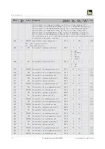
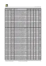
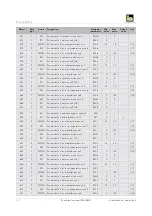
iDM EIB/KNX, Technical Documentation Installation Instruction
The Eibmarkt EIB/KNX product is accompanied by a comprehensive user manual, which can be easily accessed and downloaded for free from our website. This essential manual provides step-by-step instructions and valuable insights to ensure a smooth and successful installation process, enhancing your overall experience with our product.
Share
Download

Reviews:
No comments
Related manuals for EIB/KNX
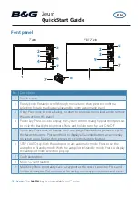
Zeus2 series
Brand: B&G Pages: 8
Zeus3S
Brand: B&G Pages: 51
H5000 Pilot
Brand: B&G Pages: 18
Zeus3S
Brand: B&G Pages: 140

23 Series
Brand: Navigon Pages: 2

PCM-3291
Brand: Advantech Pages: 13

GPS-TS
Brand: 3Sense Pages: 14

jlr-21
Brand: Japan Radio Co. Pages: 148
GPS HD
Brand: MotionX Pages: 32

EM-406
Brand: Globalsat Pages: 9

ST240
Brand: SunTech Pages: 7

WGT-168
Brand: Wintec Pages: 34

StreetPilot i5
Brand: Garmin Pages: 68

M588
Brand: Rope Pages: 12

M-DVD6560
Brand: Macrom Pages: 28

P 3101
Brand: Pentagram Pages: 22

GS170
Brand: danew Pages: 14
Compasseo 800
Brand: Packard Bell Pages: 10


