background image


Label Printer 


Service Manual 


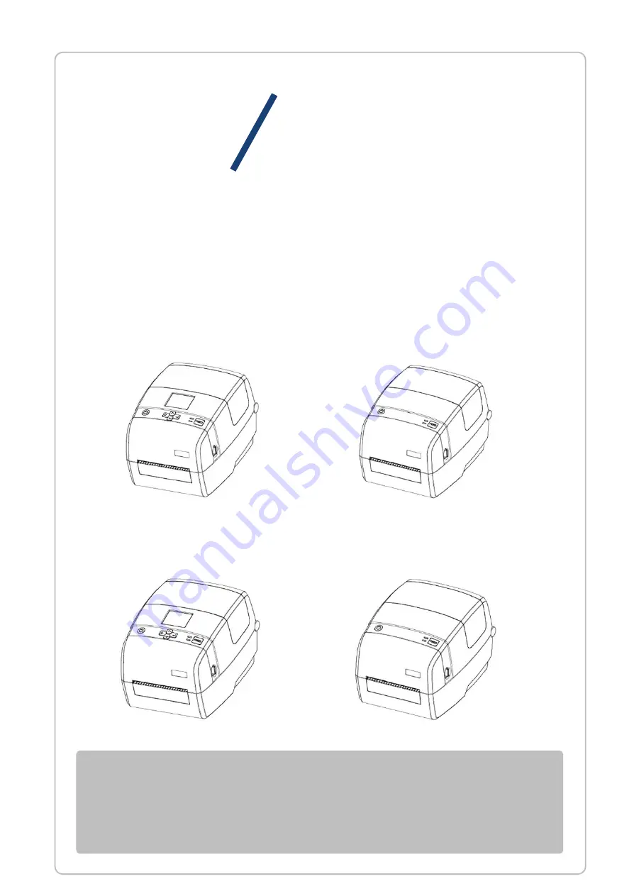
ID4    IE4 Series


IE4P 

IE4S 

ID4S 

ID4P 

Summary of Contents for ID4 Series

Page 1: ...Label Printer Service Manual ID4 IE4 Series IE4P IE4S ID4S ID4P...

Page 2: ...v 1 0 1 Document Change Record This page records changes to this document The document was originally released as Revision 1 0 Version Number Date Description of Change Rev 1 0 2018 01 17 First Editio...

Page 3: ...e for periodic inspections and maintenance procedure to be executed by service person It is not intended for the general user Users of this manual should have a basic knowledge and understanding of En...

Page 4: ...developing on the device Never start a service when your hands are wet This will prevent an electric shock as well as rust developing on the device Always wear a wristband to prevent a damage by elect...

Page 5: ...7 1 6 Arrow Key Module 29 1 7 Feed Button Module 31 1 8 Upper photoelectric Module 35 1 9 Lower Photoelectric Module 37 1 10 Micro switch Module 41 1 11 Ribbon Detection Module 43 1 12 Left and Right...

Page 6: ...ID4 IE4 Series Service Manual Rev 1 0 5 CHAPTER 3 PARTS LIST 59 3 1 The Exploded View 60 3 2 Service Parts 68...

Page 7: ...the device Always wear a wrist strap to prevent the damage by electrostatic discharge Assembly is the reverse of disassembly unless otherwise specified Assembly is the reverse of disassembly unless ot...

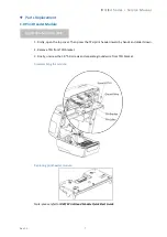
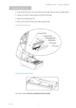
Page 8: ...n press the TPH print header inward by hands and slide it down 2 Remove TPH from TPH bracket 3 Finally unscrew the 3 0 5 0 screws and separate ground wire from TPH bracket Disassembling the module Rep...

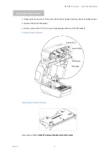
Page 9: ...header inward by hands and slide it down 2 Remove TPH from TPH bracket 3 Finally unscrew the 3 0 5 0 screws and separate ground wire from TPH bracket Disassembling the module Replacing print header m...

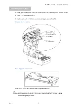
Page 10: ...ds and slide it down 2 unscrew two 3 0 6 0 screws and remove TPH from TPH bracket 3 Remove the TPH cable from TPH 4 Finally unscrew the 3 0 5 0 screw and take out ground wire Disassembling the module...

Page 11: ...he TPH cable from TPH 3 Finally unscrew the 3 0 5 0 screw and remove the ground wire from TPH Disassembling the module Replacing print header module Note please refer to iE4S Print Head Module Quick S...

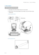
Page 12: ...ule 1 Using nippers remove the tip of platen sleeves from the main body 2 Rotate the platen roller sleeves 90 degrees counterclockwise and pull out the two sleeves simultaneously Disassembling the mod...

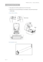
Page 13: ...ng nippers remove the tip of platen sleeves from the main body 2 Rotate the platen roller sleeves 90 degrees counterclockwise and pull out the two sleeves simultaneously Disassembling the module Repla...

Page 14: ...otor Module 1 Firstly unscrew four 3 0 8 0 screws to separate lower cover from lower bracket by cross screwdriver 2 Secondly unscrew four 4 0 8 0 screws to remove motor module Disassembling the module...

Page 15: ...al Rev 1 0 14 1 Firstly unscrew four 3 0 8 0 screws to separate lower cover from lower bracket 2 Secondly unscrew four 4 0 8 0 screws to remove motor module Disassembling the module Replacing motor mo...

Page 16: ...al Rev 1 0 15 1 Firstly unscrew four 3 0 8 0 screws to separate lower cover from lower bracket 2 Secondly unscrew four 4 0 8 0 screws to remove motor module Disassembling the module Replacing motor mo...

Page 17: ...al Rev 1 0 16 1 Firstly unscrew four 3 0 8 0 screws to separate lower cover from lower bracket 2 Secondly unscrew four 4 0 8 0 screws to remove motor module Disassembling the module Replacing motor mo...

Page 18: ...nscrew four 3 0 8 0 screws to separate lower cover from lower bracket 2 Then unscrew the 2 0 3 0 screw to remove the COM port baffle 3 Finally unscrew four 3 0 6 0 screws remove the main board from lo...

Page 19: ...ID4 IE4 Series Service Manual Rev 1 0 18 Replacing main board Replacing button battery Replacing core board...

Page 20: ...to separate lower cover from lower bracket 2 Then unscrew the 2 0 3 0 screw to remove the COM port baffle 3 Finally unscrew four 3 0 6 0 screws remove the main board from lower bracket 4 Take out the...

Page 21: ...ID4 IE4 Series Service Manual Rev 1 0 20 Replacing main board Replacing button battery Replacing core board...

Page 22: ...to separate lower cover from lower bracket 2 Then unscrew the 2 0 3 0 screw to remove the COM port baffle 3 Finally unscrew four 3 0 6 0 screws remove the main board from lower bracket 4 Take out the...

Page 23: ...ID4 IE4 Series Service Manual Rev 1 0 22 Replacing main board Replacing button battery Replacing core board...

Page 24: ...to separate lower cover from lower bracket 2 Then unscrew the 2 0 3 0 screw to remove the COM port baffle 3 Finally unscrew four 3 0 6 0 screws remove the main board from lower bracket 4 take out the...

Page 25: ...ID4 IE4 Series Service Manual Rev 1 0 24 Replacing main board Replacing button battery Replacing core board...

Page 26: ...upper cover from the upper bracket 2 Secondly unscrew four 3 0 6 0 screws to remove the PCB cover from the upper cover 3 Then unscrew four 3 0 6 0 screws remove the LCD Bracket from upper cover 4 Fina...

Page 27: ...er from the upper bracket 2 Secondly unscrew four 3 0 6 0 screws to remove the PCB cover from the upper cover 3 Then unscrew four 3 0 6 0 screws remove the LCD Bracket from upper cover 4 Finally take...

Page 28: ...Series Service Manual Rev 1 0 27 1 5 Power Switch Module 1 Unscrew two 3 0 6 0 screws 2 Remove the keypad of power switch from upper cover Disassembling the module Replacing keypad Applicable Module i...

Page 29: ...ID4 IE4 Series Service Manual Rev 1 0 28 1 Unscrew two 3 0 6 0 screws 2 Remove the keypad of power switch from upper cover Disassembling the module Replacing keypad Applicable Module iE4P iE4S...

Page 30: ...nual Rev 1 0 29 1 6 Arrow Key Module 1 Unscrew four 3 0 6 0 screws remove key press panel from upper cover 2 Take out the spring of the keypad and the arrow key Disassembling the module Replacing keyp...

Page 31: ...Service Manual Rev 1 0 30 1 Unscrew four 3 0 6 0 screws remove key press panel from upper cover 2 Take out the spring of the keypad and the arrow key Disassembling the module Replacing keypad Applicab...

Page 32: ...Module 1 Unscrew two 2 5 6 0 screws remove cable fastener from upper cover 2 Then unscrew two 3 0 6 0 screws to remove the keypad from upper cover Take out the feed button shade holder and LED Disasse...

Page 33: ...econdly unscrew four 3 0 6 0 screws to remove PCB cover from upper conver 3 Then unscrew two 2 5 6 0 screws and take out the cable fastener 4 Finally unscrew two 3 0 6 0 screws remove PCB board from u...

Page 34: ...l Rev 1 0 33 1 Unscrew two 2 5 6 0 screws by screwdriver to remove cable fastener 2 Then unscrew two 3 0 6 0 screws remove keypad feed button shade holder and LED Disassembling the module Replacing ke...

Page 35: ...t 2 Secondly unscrew four 3 0 6 0 screws and remove PCB cover from upper cover 3 Then unscrew two 2 5 6 0 screws take out the cable fastener 4 Finally unscrew two 3 0 6 0 screws to remove PCB board fr...

Page 36: ...c Module 1 Unscrew three 2 5 5 0 screws and remove the bracket cover of upper photoelectric from the upper photoelectric 2 Manually remove the PCB board of the upper photoelectric Disassembling the mo...

Page 37: ...rew three 2 5 5 0 screws and remove the bracket cover of upper photoelectric from the upper photoelectric 2 Manually remove the PCB board of the upper photoelectric Disassembling the module Replacing...

Page 38: ...al Rev 1 0 37 1 9 Lower Photoelectric Module 1 Unscrew four 3 0 6 0 screws remove the rack cover from lower bracket 2 Manually remove the lower photoelectric and locking chip Disassembling the module...

Page 39: ...ID4 IE4 Series Service Manual Rev 1 0 38 Replacing lower photoelectric module...

Page 40: ...es Service Manual Rev 1 0 39 1 Unscrew four 3 0 6 0 screws remove the rack cover from lower bracket 2 Manually remove the lower photoelectric and locking chip Disassembling the module Applicable Modul...

Page 41: ...ID4 IE4 Series Service Manual Rev 1 0 40 Replacing lower photoelectric module...

Page 42: ...es Service Manual Rev 1 0 41 1 10 Micro switch Module 1 Unscrew the 2 0 5 0 6 0 screw by screwdriver 2 Manually remove the micro switch Disassembling the module Replacing micro switch Applicable Modul...

Page 43: ...ID4 IE4 Series Service Manual Rev 1 0 42 1 Unscrew the 2 0 5 0 6 0 screw by screwdriver 2 Manually remove the micro switch Disassembling the module Replacing micro switch Applicable Module iE4P iE4s...

Page 44: ...e Manual Rev 1 0 43 1 11 Ribbon Detection Module 1 Unscrew the 2 0 5 0 6 0 screw by screwdriver 2 Manually remove the ribbon detection module Disassembling the module Replacing ribbon detection Applic...

Page 45: ...2 0 5 0 6 0 screw and remove the baffle and synchronized gear 2 Manually remove the springs then unscrew four 3 0 8 0 screws to separate the big gear from the roll holder 3 Place the front of the pri...

Page 46: ...and remove the baffle and synchronized gear 2 Manually remove the springs then unscrew four 3 0 8 0 screws to separate the big gear from the roll holder 3 Place the front of the printer on the desk ma...

Page 47: ...he desk 2 Remove the iWLM card cover by hand 3 Insert the iWLM card into left port then press inward 4 Coved with iWLM card cover after finishing WiFi loading Disassembling the module Replacing iWLM m...

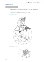
Page 48: ...er Module 1 Open the top cover of the printer 2 Thumb the hooks and then lift the platen vertically 3 Hold the front cover and remove it horizontally Load the cutter Cutter Note please refer to the E4...

Page 49: ...er Module 1 Open the top cover of the printer 2 Thumb the hooks and then lift the platen vertically 3 Hold the front cover and remove it horizontally Load the peeler Peeler Note please refer to the E4...

Page 50: ...ID4 IE4 Series Service Manual Rev 1 0 49 1 16 Power Cord 1 17 Power Adapter...

Page 51: ...ID4 IE4 Series Service Manual Rev 1 0 50 1 18 External Paper Roll Stand 1 Unscrew six 3 0 4 0 screws by screwdriver 2 Manually remove the side panel from bottom panel...

Page 52: ...ID4 IE4 Series Service Manual Rev 1 0 51 Module Purchase for Service...

Page 53: ...ID4 IE4 Series Service Manual Rev 1 0 52 Chapter 2 Troubleshooting CONTENT 2 1 Troubleshooting Procedure 2 2 Troubleshooting 2 3 Service Process...

Page 54: ...there are multiple phenomena take all the corresponding items into consideration This allows you to specify a hidden defective part Cause List all the possible causes and judge the trouble cause throu...

Page 55: ...ck power Switch 2 Faulty Sensor Phenomenon Description Does not detect presence of paper Cause Faulty paper sensor Check Method Check whether the ERROR lamp flickers when paper is out Remedy Replace t...

Page 56: ...head cable to connector properly Check Method Check the connection of the thermal head connector Cause Thermal head is broken Remedy Replace the thermal head Print blurred or uneven Cause Thermal hea...

Page 57: ...platen properly Cause Paper feed failure Check Method Check if the paper is jamming or torn and caught in the paper path Remedy Eliminate unnecessary paper in the paper path and set paper properly Cau...

Page 58: ...Rev 1 0 57 2 3 Service Process...

Page 59: ...Rev 1 0 58...

Page 60: ...n revised version mark has been entered in this column 3 PARTS NAME Parts names must be indicated when ordering replacement parts 4 Q TY This column shows the number of the part used indicated in the...

Page 61: ...ID4 IE4 Series Service Manual Rev 1 0 60 3 1 The Exploded View ID4P...

Page 62: ...ID4 IE4 Series Service Manual Rev 1 0 61...

Page 63: ...ID4 IE4 Series Service Manual Rev 1 0 62 ID4S...

Page 64: ...ID4 IE4 Series Service Manual Rev 1 0 63...

Page 65: ...ID4 IE4 Series Service Manual Rev 1 0 64 IE4P...

Page 66: ...Rev 1 0 65...

Page 67: ...ID4 IE4 Series Service Manual Rev 1 0 66 IE4S...

Page 68: ...ID4 IE4 Series Service Manual Rev 1 0 67...

Page 69: ...14 LCD Bracket 1 15 Screw 3 0 6 0PBHO 4 To Screw the LCD bracket 16 Cable Fastener 1 17 Screw 2 5 6 0PBHO 2 To screw the cable fastener 18 PCB Cover 1 19 Screw 3 0 6 0PBHO 4 To screw the PCB cover 20...

Page 70: ...2 0 5 0BBHO 2 To screw buffer 45 Buffer 1 46 Buffer Cover 1 47 Screw 3 0 6 0PBHO 4 To screw the buffer cover 48 Synchronized Gear 1 49 Right Roll Holder 1 50 Left Roll Holder 1 51 Baffle 1 52 Screw 2...

Page 71: ...3 Hook 1 14 Screw 3 0 8 0PBHO 6 To screw upper cover upper bracket 15 Screw 3 0 6 0PBHO 2 To screw the PCB board of LED 16 LED PCB board 1 17 Screw 2 5 5 0PBHO 3 To screw the bracket cover of the uppe...

Page 72: ...ronized Gear 1 42 Right Roll Holder 1 43 Left Roll Holder 1 44 Baffle 1 45 Screw 2 0 5 0 6 0PWBHO 1 To screw the baffle 46 Big Rack 2 47 Spring 2 48 Screw 3 0 8 0PBHO 4 To screw the big rack 49 Core b...

Page 73: ...4 LCD Bracket 1 15 Screw 3 0 6 0PBHO 4 To Screw the LCD bracket 16 Cable Fastener 1 17 Screw 2 5 6 0PBHO 2 To screw the cable fastener 18 PCB Cover 1 19 Screw 3 0 6 0PBHO 4 To screw the PCB cover 20 H...

Page 74: ...ew the motor module 39 Right Label Guide 1 40 Left Label Guide 1 41 Lower Photoelectric 1 42 Locking Tab 1 43 Right Rack 1 44 Left Rack 1 45 Screw 3 0 6 0PBHO 2 To screw the left and right rack 46 Scr...

Page 75: ...Unit 1 61 COM port Baffle 1 62 Screw 2 0 3 0PMHZn 1 To screw the COM port baffle 63 WIFI Bluetooth iWLM 1 64 Screw 3 0 6 0PBHO 4 To screw the main board unit 65 Lower cover 1 66 SD cover 1 67 Screw 3...

Page 76: ...fastener 11 PCB Cover 1 12 Screw 3 0 6 0PBHO 4 To screw the PCB cover 13 Hook 1 14 Screw 3 0 8 0PBHO 6 To screw upper cover upper bracket 15 Screw 3 0 6 0PBHO 2 To screw the PCB board of LED 16 LED P...

Page 77: ...eft and right rack 39 Screw 2 0 5 0BBHO 2 To screw buffer 40 Buffer 1 41 Buffer Cover 1 42 Screw 3 0 6 0PBHO 4 To screw the buffer cover 43 Synchronized Gear 1 44 Right Roll Holder 1 45 Left Roll Hold...

Page 78: ...ID4 IE4 Series Service Manual Rev 1 0 77 59 SD cover 1 60 Screw 3 0 8 0PBHO 4 To screw the lower cover and lower bracket...

Reviews: