background image


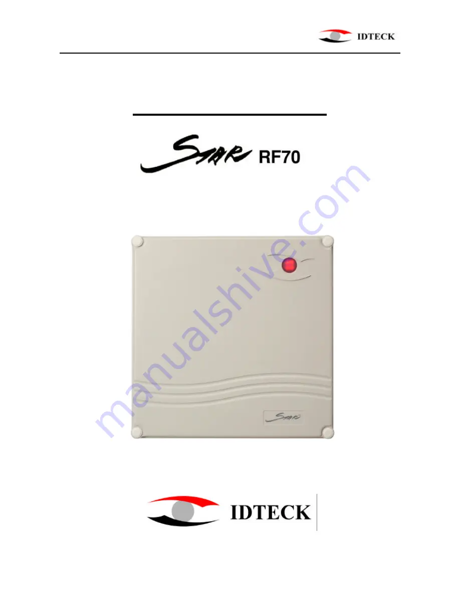
S T A R   R F 7 0                                                                                       P R O X I M I T Y   R E A D E R


20021214 


         USER’S MANUAL 


USER’S MANUAL 


Proximity Reader


Summary of Contents for STAR RF70

Page 1: ...STAR RF70 P R O X I M I T Y R E A D E R 20021214 USER S MANUAL 1 USER S MANUAL Proximity Reader ...

Page 2: ...oduction page 3 2 Identifying supplied parts page 3 3 Specification page 3 4 Installation page 4 5 Jumper location page 5 6 Wire Color Table of RF70 page 6 7 Wire Connection to Controller page 6 8 Operation page 7 9 FCC Registration Information page 7 10 Warranty and Service page 8 ...

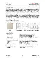
Page 3: ...ver RF70 is mounted to different materials Thetwo colorLEDofgreenand red and the inside beeper sound will guarantee you accurate and reliable system operations 2 Identifying supplied parts Please unpack and check the contents of the box RF70 User s Manual Mounting Bracket Optional purchase 3 Specification Read Range Up to 28 70cm with IDC170 cards Up to 5 foot 1 5m with IDA150 cards Up to 7 foot 2...

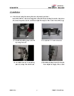
Page 4: ...mountingplate and install the mounting bracket to the pole as shown in the photos below and then adjust the angle of the reader toward the tags 1 Install mounting plate to RF70 2 Assemble U bolt to bracket by using 8 screws 3 Assemble bracket to mounting 4 Install mounting bracket to the pole plate by using 2 hex bolts nuts then adjust the angle of the reader ...

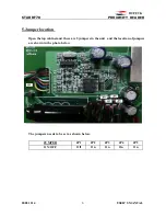
Page 5: ...21214 USER S MANUAL 5 5 Jumper location Open the top cabinet and there are 5 jumpers in the unit and thelocation of jumpers are shown in the photo below The jumpers needs to be set as shown below JUMPER JP1 JP2 JP3 JP4 JP5 ON OFF Off On On On On ...

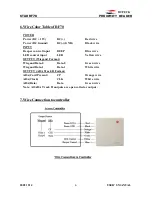
Page 6: ...NPUT Beeper control input BEEP Blue wire LED control input LED Yellow wire OUTPUT Wiegand Format Wiegand Data 0 Data 0 Green wire Wiegand Data 1 Data 1 White wire OUTPUT ABA Track II Format ABA Card Present CP Orange wire ABA Clock CLK White wire ABA Data Data Green wire Note All ABA Track II outputs are open collector output 7 Wire Connection to controller ...

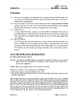
Page 7: ...main on as long as the Blue wire is connected to system ground 9 FCC REGISTRATION INFORMATION FCC REQUIREMENTS PART 15 Caution Any changes or modifications in construction of this device which are not expressly approved by the responsible for compliance could void the user s authority to operate the equipment NOTE This device complies with Part 15 of the FCC Rules Operation is subject to the follo...

Page 8: ...TD Service Center 5F Ace Techno Tower Bldg 684 1 Deungchon dong Gangsuh gu SEOUL 157 030 KOREA Tel 82 2 2659 0055 Fax 82 2 2659 0086 E mail webmaster idteck com Web site www idteck com IN THE UNITED STATES RF LOGICS Inc Service Center 3026 Scott Blvd SANTA CLARA CA95054 Tel 408 980 0001 Fax 408 980 8060 E mail rflogics rflogics com Web site www rflogics com Please use the original container or pac...

Reviews: