background image


User’s Manual 


13.56MHz Contactless Smart Card Reader 


Summary of Contents for Star SR10

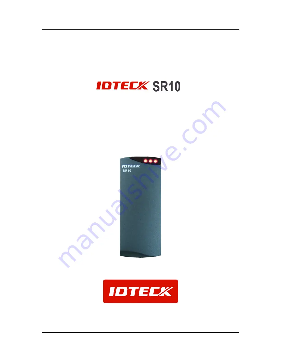
Page 1: ...User s Manual 13 56MHz Contactless Smart Card Reader ...

Page 2: ... 3 2 General 3 3 Features 4 4 Identifying Supplied Parts 4 5 Specification 5 6 Installation 6 7 Wire Color Table 8 8 Output Format 9 9 Wire Connection to Access Controller 10 10 Operation 10 11 FCC Registration Information 12 12 Warranty and Service 13 ...

Page 3: ...ous voltages or other risks Also incorrect reassembly can cause electric shock when the unit is subsequently used 8 Unplug this product from the Direct Current DC power source and refer to qualified service personnel under these conditions a When the power supply cord or plug is damaged or frayed b If liquid has been spilled on the product c If the product does not operate normally after following...

Page 4: ...nal LED Control External Buzzer Control Easy to install on Mullion Mounting suitable Solid Epoxy Potted Waterproof IP65 IP66 Warranty Life Time Reverse Polarity Protection Compatible Software Smart Card Read Write Software Compatible Controller iCON100SR iTDC SR Third Party Controller 4 Identifying Supplied Parts Please unpack and check the contents of the box Reader Module SR10 Bezel User s Manua...

Page 5: ... 65 31 to 149 Operating Humidity 10 to 90 relative humidity non condensing Color Material Dark Peal Gray Polycarbonate Dimension W x H x T 47mm X 115mm X 22 mm 1 8 X 4 5 X 0 88 Weight 150g 0 33lbs Index of Protection IP65 IP66 Certification FCC CE MIC Card reading range by Contactless Smart Mifare Reader Series Model ISC80 ISK50 IMC135 IHC80 SR10 SR30 SRK101 4 inch 10cm 2 inch 5cm SR10B SR30B SRK1...

Page 6: ... from the Reader excite field and affects the signal being received from the card by re directing excite field transmissions into the receiver circuitry Moving the Reader away from the metal objects reduces energy loss Try to limit the amount of metallic materials installed near the SR10 Use a plastic electrical box if possible When installing the Reader on metal door frame add Isolation Spacers b...

Page 7: ...ck to back on a wall that will separate the two readers by eight inches 20cm or less a metal plate for example Reader isolation plate metal wall must be placed between the readers To obtain the maximum read range mount each proximity reader onto one or more Isolation Spacers Two readers can simultaneously read the same badge or tag if the distance between the two readers is less than 8 inches 20cm...

Page 8: ...A Track II CP Out Orange Wiegand Data 0 Out ABA Track II Data Out Green Wiegand Data 1 Out ABA Track II Clock Out White Buzzer Control In Blue LED Control In Yellow 34 26bit Wiegand Select In Gray RS232 TX Purple Not Connect Brown Please cut out tail connector before installation ...

Page 9: ...535 Bit 2 25 4byte ID number 0000000001 4 294 967 295 Bit 26 Odd parity of bit 14 bit 25 Bit 34 Odd parity of bit 18 bit 33 2 Timing diagram 8 2 RS232 Output format Optional START 0x02H DATA 10 or 8 characters END 0x03H LRC 3 5V 0 5V 100uS 1mS Data 0 100uS 100uS Data 1 3 5V 0 5V 5V 5V 0V 0V 15V 15V 3V 3V Space 0 Mark 1 8 Data Bits 2 Stop Bits Indeterminate Region Data packet corresponding to ASCII...

Page 10: ...anges the color to red simultaneously then to green again for next reading All 3 LEDs are off when you have access to card and then are on orderly from left 10 4 Buzzer Control When the reader reads a proximity card only one beep sound generates in normal operating mode but you can generate more beep sounds to distinguish whether the access is granted or denied To generate more beeps you may contr...

Page 11: ...mmed off It is useful when there are controllers which deal with 3 byte data only as most of existing controllers do For 3 byte outputs connect the 34 bit 26 bit selection input Gray wire to ground Caution It is unavoidable that some card numbers are duplicated in 3 byte output e g 34bit 0x21 0x97 0x32 0xBC Hexa 0563557052 Decimal 26bit 0x32 FAC 0x97 0x21 ID number Hexa 050 FAC 38689 ID number Dec...

Page 12: ...rsuant to Part 15 of the FCC Rules These limits are designed to this equipment generates uses and can radiate radio frequency energy and if not installed and used in accordance with the instructions may cause harmful interference to radio communications However there is no guarantee that interference will not occur in a particular installation If this equipment does cause harmful interference to r...

Page 13: ...0501 Tel 310 782 8383 Fax 310 782 8298 E mail rflogics rflogics com Website www rflogics com Hong Kong Branch IDTECK Hong Kong 12 F B2B Centre No 36 Connaught Road West Hong Kong Tel 852 2581 9580 Fax 852 2234 5150 E mail alchu qala com hk Website www ristarhk com Please use the original container or pack the unit s in a sturdy carton with sufficient packing to prevent damage include the following...

Page 14: ...14 MEMO ...

Page 15: ...15 MEMO ...

Page 16: ...RSR10HE2X The specification contained in this manual are subject to change without notice at any time 5F Ace Techno Tower B D 684 1 Deungchon Dong Gangseo Gu Seoul 157 030 Korea Tel 82 2 2659 0055 Fax 82 2 2659 0086 E mail webmaster idteck com ...

Reviews: