RACK-3200G QIG IEI Technology Corp.
Page 1
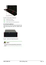
RACK-3200G
4U Rackmount Chassis
Version: 1.0
Quick Installation Guide
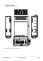
ABOUT THE RACK-3200G
The 4U, metal RACK-3200G AT/ATX compatible rackmount
industrial chassis is designed to operate reliably in industrial
environments where it will be exposed to dust, wide temperature
variations, and shocks and vibrations, among other things.
SPECIFICATIONS
Form Factor:
Standard 4U, 19” wide
SBC Form Factor:
Full-size, slot CPU cards
Construction:
Metal
Slots Number:
20-slot
Cooling:
4 x 8cm fans
Drive Bays:
o
6 x 5.25” Optical drives
o
1 x 3.5” FDD (floppy disk drive)
Dimensions (DxWxH):
o
674mm x 431mm x 176mm
Operating Temperature:
0~40°C
Relative Humidity:
5~95%
Vibration:
o
5-17Hz, 0.1” double amplitude displacement
o
17-640Hz, 1.5G acceleration peak to peak
Shock:
10G acceleration peak to peak
PACKING LIST
When you unpack the chassis, make sure the following items have
been shipped.
1 x Quick Installation Guide
1 x Power cord
2 x Handles and handle plates
1 x Screw set
2 x Keys
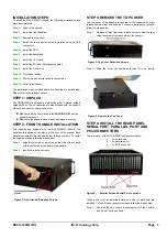
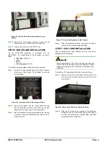
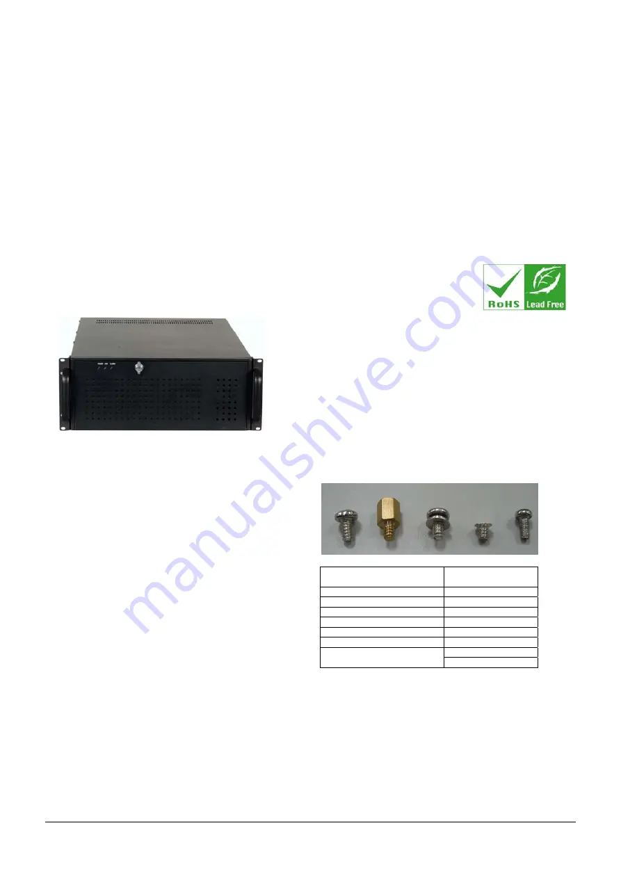
DETAILS OF INCLUDED SCREWS
The attached screw set includes five types of screws. Screws used
for chassis installation are shown below.
1 2 3 4 5
Peripherals/Parts
Screw Label (refer to
the picture above)
5.25” Optical Drives
5
3.5” FDD
5
3.5” HDD
1
2.5” HDD
4
Power Supply Unit
1
Rackmount Bracket
3
3
Backplane
2
Table 1:
Screws for Peripheral/Parts