background image

____________________________________________________________________________________________________________ 

P/N 900256-00 Rev. A                                       Rev 3/18/14 Page 1 of 7


IHP: RC-S-1 


Cat. No. H8860

 Model:


RC-S-1 


INSTALLATION AND OPERATION INSTRUCTIONS


INTRODUCTION 

This  remote  control  system  was  developed  to  provide  a  safe,  reliable  and  user-friendly  remote  control  system  for  gas  heating 
appliances.  This all battery system operates independently of household current.  The system operates on radio frequencies with non-
directional signals.  The SYSTEM’s operating range is approximately 20-foot range.  The system operates on one of 1,048,576 security 
codes that are programmed into the transmitter at the factory; the remote receiver's code must be matched to that of the transmitter 
prior to initial use.  


TRANSMITTER 


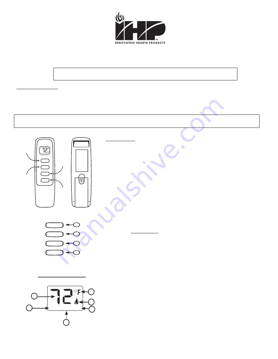
This  remote  control  SYSTEM  offers  the  user  a  battery-operated  remote  control  that 
operates most millivolt gas valves used in some heater rated gas logs, gas fireplaces 
and other gas heating appliances. 
 
The transmitter operates on (2) 1.5V AAA batteries. 
 
It is recommended that ALKALINE batteries always be used for longer battery life and 
maximum operational performance. 
 
Before  using  the  transmitter,  install  the  (2)  AAA  transmitter  batteries  into  the  battery 
compartment. (Use caution that batteries are installed in the proper direction) 


KEY SETINGS 


1.  ON         - Operates unit to on position, Manually ON. 
2.  OFF         - Operates unit to off position, Manually OFF. 
3.  TIMER      - Changes unit from manual mode to timer mode. 
4.  SET          - Sets the timer in minutes. 


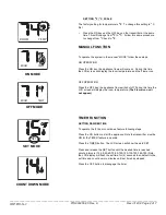
1.  DISPLAY 


Indicates CURRENT room temperature

2. 

0

 F

 OR 

C  

Indicates degrees Fahrenheit or Celsius.


3.  FLAME


Indicates burner/valve in operation.


4.  ROOM


Appears when LCD screen is on.


5.  TEMP    

Appears when LCD screen is on.


6.  SET  


Appears when setting the timer.


IF YOU CANNOT READ OR UNDERSTAND THESE INSTALLATION INSTRUCTIONS, DO 

NOT ATTEMPT TO INSTALL OR OPERATE  

ON

TIMER

OFF

BUTTON

WALL CLIP

SLOT

BATTERY

COMPARTMENT

FRONT

BACK

OFF

SET

ON

BUTTON

TIMER

BUTTON

SET

BUTTON

ROOM

TEMP


ROOM

LCD - Liquid Crystal Display

TEMP

1

2

3

SET

4

5

6


ON

TIMER

OFF

SET

1

2

3

4


Review 

COMMUNICATION SAFETY SECTION

 under TRANSMITTER section.  

These safety features shut down the fireplace system 

when a potentially unsafe condition exists.


Summary of Contents for RC-S-1

Page 1: ...perates on 2 1 5V AAA batteries It is recommended that ALKALINE batteries always be used for longer battery life and maximum operational performance Before using the transmitter install the 2 AAA transmitter batteries into the battery compartment Use caution that batteries are installed in the proper direction KEY SETINGS 1 ON Operates unit to on position Manually ON 2 OFF Operates unit to off pos...

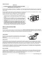
Page 2: ... and the Flame icon ON MODE OFF OPERATION Press the OFF key the appliance flame will shut off During this time the LCD screen will display the room temperature The Flame icon will not appear OFF MODE TIMER FUNCTION SETTING DESIRED TIME To operate the 3 hour count down feature following steps Press the ON button to start the appliance Note the transmitter must be ON for the TIMER feature to operate...

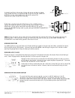
Page 3: ...ece of electronic equipment the remote receiver should be kept away from temperatures exceeding 130ºF inside the receiver case Battery life is also significantly shortened if batteries are exposed to high temperatures HEARTH MOUNT The remote receiver can be placed on the fireplace hearth or under the fireplace behind the control access panel Locate the receiver where it is not exposed to Extreme h...

Page 4: ... remote should install the remote control system Incorrect wiring connections WILL cause damage to the gas valve or electronic module operating the gas appliance and may also damage the remote receiver WIRING MILLIVOLT VALVES The remote receiver is connected to the millivolt valve using the TH thermostat terminals on the terminal block on the millivolt gas valve Connect 18 gage solid or stranded w...

Page 5: ... This remote control includes a CHILDPROOF LOCK OUT feature that allows the user to LOCK OUT operation of the appliance from the TRANSMITTER SETTING LOCK OUT CP To activate the LOCK OUT feature press and hold the ON button and the TIMER button at the same time for 5 seconds The letters CP will appear in the TEMP frame on the LCD screen To disengage the LOCK OUT press and hold the ON button and the...

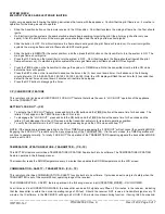
Page 6: ...he transmitter ANY button and release The receiver will emit several beeps indicating that the transmitter s code has been accepted into the receiver The microprocessor that controls the security code matching procedure is controlled by a timing function If you are unsuccessful in matching the security code on the first attempt wait 1 2 minutes before trying again this delay allows the microproces...

Page 7: ...within 90 days of the date of failure Notices should be directed to the IHP Warranty Department at 1508 Elm Hill Pike Suite 108 Nashville TN 37210 or visit our website at www IHP us com SPECIFICATIONS BATTERIES Transmitter 2 1 5 volt AAA t batteries Remote Receiver 6 volts 4 AA 1 5 Alkaline batteries FCC ID No s transmitter K9LSP1001TH receiver K9L3301RX Operating Frequency 303 8 MHZ Canadian IC I...

Reviews: