background image

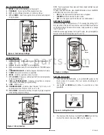
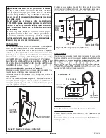
Figure 1 - Remote Control Battery Compartment

MODE

    BATTERY

COMPARTMENT

BACK

FRONT

SET

PROG

PROG MODE

SET

TSRC TOUCHSCREEN REMOTE CONTROL KIT

[FOR USE WITH MODELS ALPHA32/36, GAMMA26, BLAZE&GLOW18/24, MAGNIFLAME24/30, MULTI-SIDED27 NORTHERNOAK27, DUAL-FLAME EOS18, SHERIDAN18/24, 
RIOLIGHTS24/30, VRT4032/36, VCT4032/36, VCM3026, CIS VF, GLOW-RAMP BGE18/24, MULTI-SIDED FVFM27, VF18/24, DUAL BURNER VD1824, ODYSSEY36/42, 
VRE3036/42, CHELSEA21, CONCORD26]

TSRC TOUCHSCREEN 

REMOTE CONTROL KIT

P/N 127160-01
Rev. B, 04/2017

HEARTH PRODUCTS

KITS AND ACCESSORIES

The transmitter operates with (4) AAA 1.5V batteries that are included. 
Install the batteries supplied with the unit into the battery compartment. 
It is recommended that ALKALINE batteries always be used for this 
product. 

Be sure the batteries are installed with the (+) and (-) ends 

facing the correct direction.

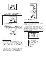
When you start up the remote, if a low battery signal appears or if they 
LCD screen does not illuminate when you touch it, check battery posi-
tion and if the batteries are fully charged.

Cat. No.

Model

Description

F1079

TSRC

Receiver & Touchscreen Remote Kit

KIT CONTENTS

1 ea. Remote Control
4 ea. AA 1.5 volt batteries (for receiver)
4 ea. 1 ea. Instruction Sheet

REQUIRED TOOLS AND SUPPLIES

Flat Blade Screwdriver

GENERAL INFORMATION

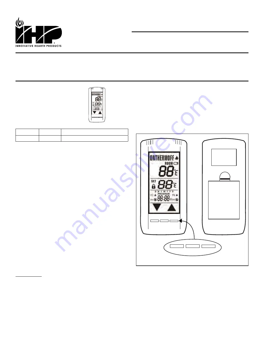
The hand-held touchscreen remote control allows the fi replace to 
be operated in a manually or thermostatically controlled mode. 

READ ALL THE STEPS BEFORE STARTING THE INSTALLATION

THE APPLIANCE MUST BE OFF AND COLD BEFORE BEGINNING.

ALL WARNINGS, PRECAUTIONS AND INSTRUCTIONS IN THE 
INSTALLATION AND OPERATION MANUAL PROVIDED WITH THE 
APPLIANCE APPLY TO THESE INSTRUCTIONS.

If you encounter any problems, need clarifi cation of these instructions
or are not qualifi ed to properly install this kit, contact you local 
distributor or dealer.

If any of these parts are missing or damaged, contact your dealer or 
IHP.us.com for referral information.

INTRODUCTION 

This remote control system was developed to provide a safe, reliable, 
and user-friendly remote control system for gas heating appliances or 
other compatible appliances. The system can be operated manually 
from the transmitter.

IHP.us.com

1

MODE

SET

PROG

f i r e - p a r t s . c o m

Summary of Contents for TSRC

Page 1: ... the batteries are fully charged Cat No Model Description F1079 TSRC Receiver Touchscreen Remote Kit KIT CONTENTS 1 ea Remote Control 4 ea AA 1 5 volt batteries for receiver 4 ea 1 ea Instruction Sheet REQUIRED TOOLS AND SUPPLIES Flat Blade Screwdriver GENERAL INFORMATION The hand held touchscreen remote control allows the fireplace to be operated in a manually or thermostatically controlled mode ...

Page 2: ...ROGRAM Turns on and off the program function 3 SET Used in different functions to confirm settings 4 UP and DOWN Used to change the time set temp and program ming functions NOTE Touch anyplace on the screen and the back light will light up and stay lit for 5 seconds To select an operation mode press the MODE button or touch the MODE SECTION at the top of the LCD screen ON turns the appliance ON th...

Page 3: ...s the appliance is turned ON and OFF 5 One of the days of the week will be flashing above the clock Select the correct day by pressing the UP and DOWN touch buttons then press SET Your time will automatically be accepted Figure 5C Figure 5A Setting the Clock Figure 6 Setting Thermostat Figure 7 Factory Presets Figure 5B Setting the Clock Figure 5C Setting the Clock THERMO UPDATING FEATURE TRANSMIT...

Page 4: ...rn OFF 4 Weekend Segment Saturday and Sunday 5 Weekday Segment Monday through Friday NOTE P1 CAN ONLY BE SET FROM 12 00AM to 12 00PM P2 CAN ONLY BE SET FROM 12 00PM to 12 00 AM Press either the PROG button or touch the Program portion of the touch screen and hold for 5 seconds the program section of the LCD screen will begin to flash P1 ON and S S Weekend Segment should be flashing Select the time...

Page 5: ...a margin of safety when the Transmitter is out of the normal 20 foot operating range of the receiver At all times and in all OPERATING MODES the transmitter sends an RF signal every 15 minutes to the receiver indicating that the transmitter is within the normal operating range of 20 feet Should the receiver NOT receive a transmitter signal every 15 minutes the receiver will begin a 2 hour 120 minu...

Page 6: ... to turn on The connectors may be wrapped with electrical tape to prevent this WARNING This remote control system must be installed exactly as outlined in these instructions Read all instructions completely before attempting installation Follow instructions carefully during installation Any modifications of this remote control or any of its components will void the warranty and may pose a fire haz...

Page 7: ...er should be relocated so it will not reach temperatures in excess of 130ºF TRANSMITTER WALL MOUNT The transmitter can be placed on a wall using the mount provided Wood Drill 1 8 pilot holes and install with screws provided Plaster Wallboard Drill 1 4 holes use a hammer to tap in the two plastic anchors Then install with the screws provided Terminal Block On Millivolt Gas Valves TH TP TP TH Thermo...

Page 8: ...e contacts are touching and ends of battery Bend metal contacts in for tighter fit Be sure receiver and transmitter is within 20 to 25 foot operating range Keep receiver from temperatures exceeding 130º F Battery life will be shortened if exposed to high temperatures If receiver is installed in a tightly enclosed metal surrounding the operating distance will be shortened Make sure the hand held tr...

Reviews: