Ihse 474 Series, User Manual
The User Manual for the IHSE 474 Series is available for free download on our website. This comprehensive manual provides detailed instructions and guidelines for operating the product effectively. Unlock the full potential of your IHSE 474 Series by accessing the manual at 88.208.23.73:8080.
Share
Download

Reviews:
No comments
Related manuals for 474 Series

CompactRIO cRIO-9074XT
Brand: National Instruments Pages: 24

FAS9000
Brand: NetApp Pages: 704
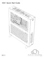
S401
Brand: Salvo Pages: 19

H5
Brand: HDPlex Pages: 34

NA221A-G3
Brand: Netstor Pages: 14
NI cRIO-9074XT
Brand: National Instruments Pages: 25

RACK-360G
Brand: IEI Technology Pages: 9

Sun Disk Shelf-24x3.5" SAS-2
Brand: Sun Oracle Pages: 22

Flex System Enterprise Chassis Airborne Contaminant Filter
Brand: IBM Pages: 12

DA2
Brand: Streacom Pages: 16

AT-MCR12
Brand: Allied Telesis Pages: 2

AT-SB4151
Brand: Allied Telesis Pages: 11

AT-MCR1
Brand: Allied Telesis Pages: 46

AT-TS24TS
Brand: Allied Telesis Pages: 64


