
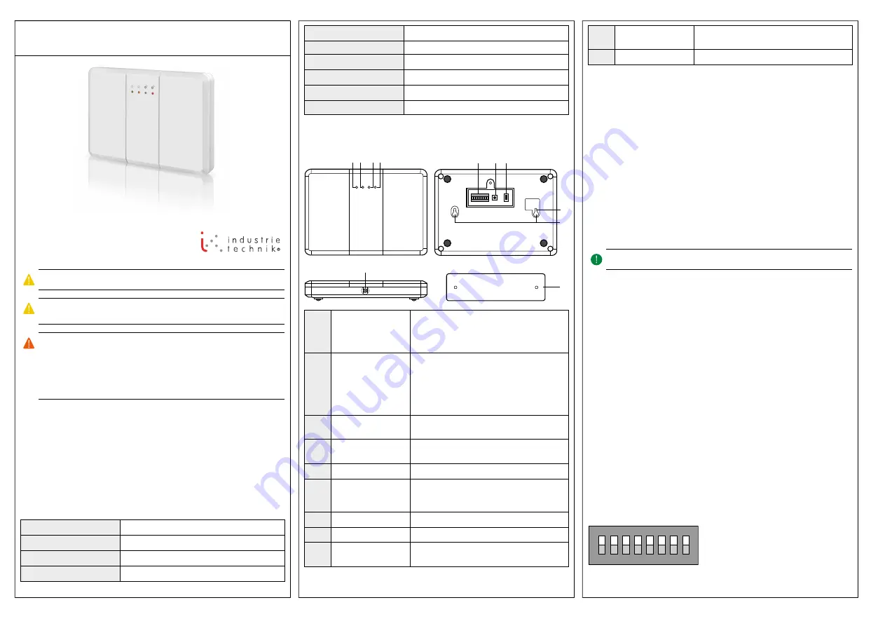
EN
INSTRUCTION
MRPW
IN20028 REV. A, 2019-11-05
Caution!
Read and understand the instruction before using the product.
Caution!
Ensure that the installation complies with local safety
regulations.
Warning!
Before installation or maintenance, the power supply must first
be disconnected in order to prevent potentially lethal electric shocks! In-
stallation or maintenance of this unit should only be carried out by quali-
fied personnel. The manufacturer is not responsible for any eventual
damage or injury caused by inadequate skills during installation, or through
removal of or deactivation of any security devices.
Function
The repeater is designed to increase the effectiveness and versatility of the
wireless system. It makes your system more powerful by increasing the
maximum possible distance between the receiver and the sensor or
transmitter.
Technical Data
Supply voltage
230 V ~ (100…240 V ~ 50/60 Hz)
Power adapter
12 V DC, 1 A
Power consumption
0.5 A
Battery backup
yes
Frequency
868 MHz
Protection class
IP30
Mounting
Wall
Material, housing
Polycarbonate (PC)
Colour, housing
RAL9010
Dimensions
185 x 130 x 30 mm
Installation
1
Power LED (green)
On: Powered by a power adapter or internal re-
chargeable battery
Flash: Internal rechargeable battery is low on
power
2
Mode LED (yellow)
On: The repeater is in
pairing mode
(MR32W)
or
clear mode
Flash (1 flash every 1 s): the repeater is in
walk
test mode
Slow flash (1 flash every 2 s): the repeater is in
pairing mode
3
Transmission: Receive
LED (blue)
The blue LED lights up when the repeater re-
ceives a signal transmission
4
Transmission: Trans-
mit LED (red)
The red LED lights up when the repeater trans-
mits a signal
5
DIP-switches
Determines the mode for the repeater
6
Function button
After activating DIP-switch 3, pressing the but-
ton will clear the previously programmed mem-
ory and resets the repeater to factory settings
7
Power switch
Recharging of the internal battery
8
Tamper switch
Tamper violation function
9
Mounting hole
For wall mounting (in combination with the
mounting bracket)
10
Power connection
(DC)
Power adapter input for supply voltage
11
Mounting bracket
For wall mounting
Mounting
The repeater can be placed on a wall or ceiling, vertically or horizontally. It is
mounted the following way:
1. Using the holes of the mounting bracket as a template, drill holes into
the mounting surface.
2. Insert the wall plugs, if fixing into plaster of brick.
3. Screw the mounting bracket to the surface.
4. Hook the repeater onto the mounting bracket (with the mounting holes
of the repeater).
Wiring
A power adapter is required to connect to a wall power outlet.
Note!
Only use the included adapter, or an equivalent.
After connecting the repeater to the supply voltage with the adapter, a long
beep will sound and the green LED will light up. The repeater will send a
failure signal to the receiver when the repeater is unplugged from the supply
voltage for 30-60 s. When the repeater is connected to the supply voltage
again for 30-60 s, the repeater will send a restore signal to the receiver.
In addition to the adapter, there is a rechargeable battery inside the
repeater, which serves as a back-up power in case of a power failure. To
recharge, slide the power switch to the ON position when the supply voltage
is connected. Power is now supplied to both the repeater and the battery. It
takes approximately 72 hours to fully charge the battery. The repeater can
detect the battery voltage. When the battery voltage is low, the green LED
will flash.
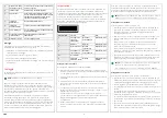
Settings
The DIP-switches determine which mode the repeater is in. A switch in the
up position indicates the ON mode, else it is in OFF mode. The DIP switch
settings are only valid when the repeater is powered. For example, DIP
switch 3 is slid to the ON position when the repeater is turned off. When the
repeater is turned on, it will not enter
clear mode
. However, if the DIP switch
3 is slid to the OFF position first, followed by sliding to the ON position, then
the repeater will enter
clear mode
.
1
2
3 4
5
6
7
8
9
11
10
1
8
7
6
5
4
3
2
ON
MRPW
1


