background image

A. 

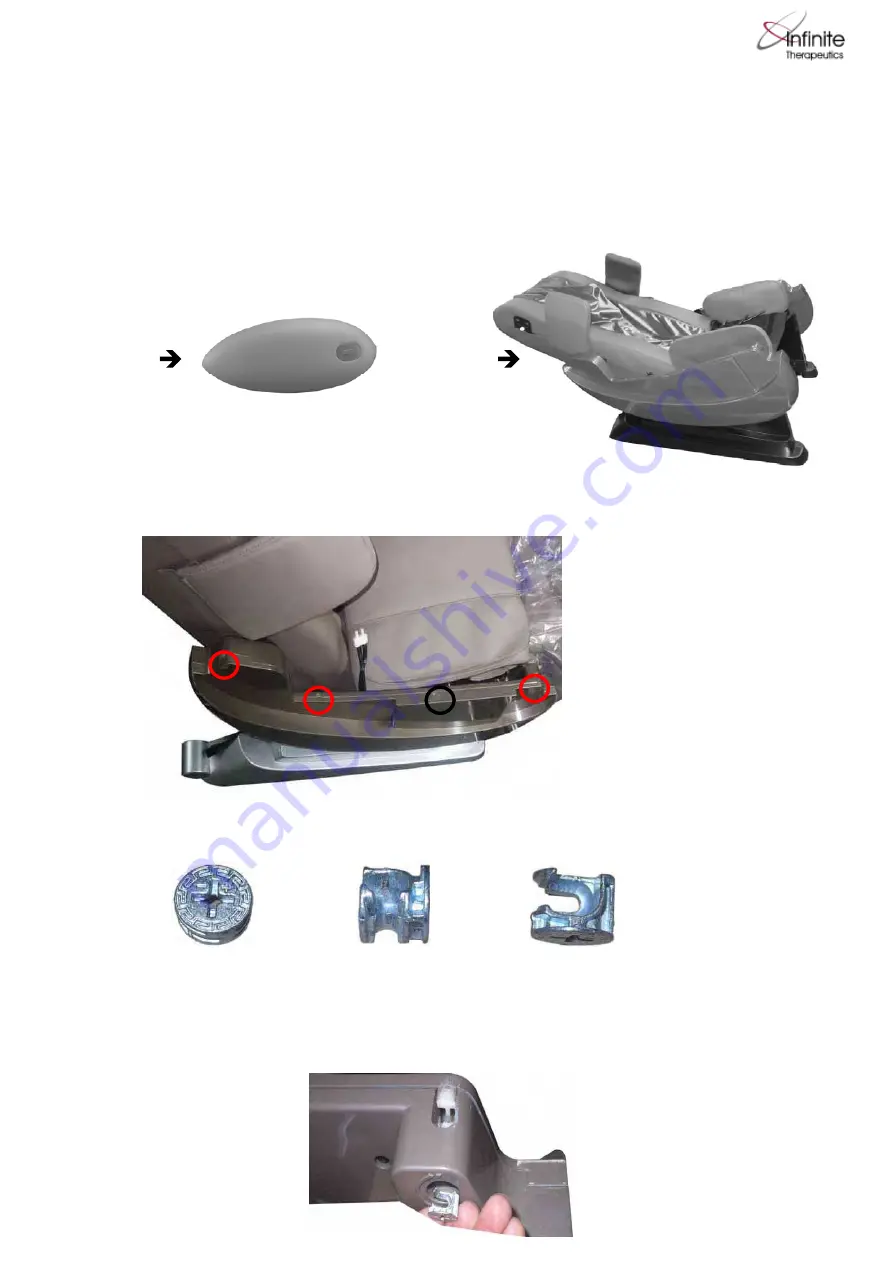
Attaching the Armrests

A1.    Remove the main body of the massage chair from its packaging.


Locate the two armrests and remove all plastic covering.

A2.    Locate the three holes (circled in red in the picture) at the base of the left armrest, attached to 


the chair.

-----------------------------------------------------

----------------------------------------------------------------------------------------

MASSAGE CHAIR ASSEMBLY

Main body

Armrest

* Although there is a hole, please 

  disregard the one circled in black.  

A3.    Look in the carton to locate the three identical screws depicted here:


A4. 


(top view)

(inverse view) 

(side view)

IT- 8500 Series Installation Guide

Fit the three screws mentioned in step A3 into the three holes mentioned in step A2. Be sure 
the screw is positioned with the + & - at the top so that the screw is positioned exactly as shown 
in the illustration.  

Summary of Contents for IT- 8500 Series

Page 1: ...MASSAGE CHAIR ASSEMBLY Main body Armrest Although there is a hole please disregard the one circled in black A3 Look in the carton to locate the three identical screws depicted here A4 top view inverse...

Page 2: ...p of the left armrest Align these three bolts with the holes depicted in A2 but do not fully set the arm rest onto the chair body Align the arm rest air hoses with the white connectors on the body of...

Page 3: ...at the same process to assemble the right armrest B2 Position the Legrest in front of the main body of the massage chair Insert the cable first then insert the air hose into their appropriate slots Ba...

Page 4: ...and 11 to 11 While looking at the chair from the front there is one air hose and one power connection in the back right of the backrest that need to be connected Connect the air hose 12 to 12 and con...

Page 5: ...akers C1 Locate the speakers and remove them from their packaging IT 8500 Series Installation Guide Place the other parts of the massage chair seat cushion back cushion head cushion etc onto the main...

Page 6: ...0 Series Installation Guide Connect the White Speaker Connector from the Speaker to the White Connector on the Chair C3 C4 Insert the three joint pins in the Shoulder Massager and Speaker into the Thr...

Page 7: ...wer plug into a power outlet Turn on the power switch Your massage chair is ready for use IT 8500 Series Installation Guide After the Joint Pins are fully inserted move down the slider to expose the L...

Reviews: