background image

Form MHD56111
Edition 2
March 1997
71296438

© 

1997 Ingersoll-Rand Company

Form MHD56111

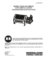
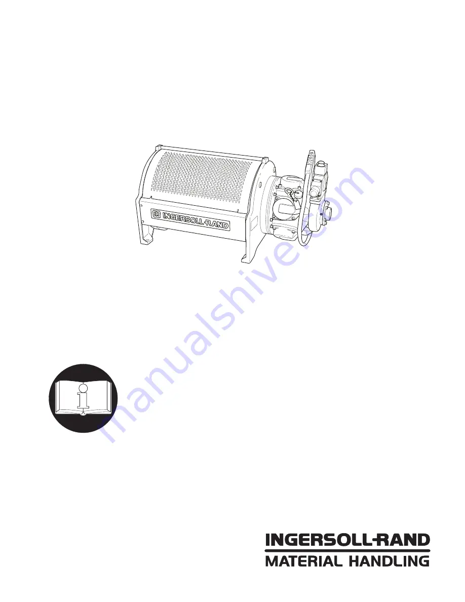
MODEL FA5A AIR WINCH

SUPPLEMENTAL SERVICE

AND MAINTENANCE INSTRUCTIONS

This manual contains important service and maintenance information.
Make this manual available to all persons responsible for the service
and maintenance of these products.

Always operate, inspect and maintain this winch in accordance with American National
Standards Institute Safety Code (ASME B30.16) and any other applicable safety codes and
regulations.

Refer all communications to the nearest Ingersoll-Rand Material Handling Office or
Distributor.

Summary of Contents for FA5A

Page 1: ...intenance information Make this manual available to all persons responsible for the service and maintenance of these products Always operate inspect and maintain this winch in accordance with American...

Page 2: ...operating the winch Danger Warning Caution and Notice Throughout this manual there are steps and procedures which if not followed may result in an injury The following signal words are used to identif...

Page 3: ...gether engaging the brake The one way clutch rides on inner and outer races The one way clutch s inner race rotates in a bearing inside the support plate and connects through the brake shaft to the ge...

Page 4: ...dump valve If no air is detected replace the orifice and dump valve assembly The disc brake is not properly lubricated The wrong amount or type of oil is in the disc brake and gearbox Remove the disc...

Page 5: ...to use a soft hammer to loosen the disc brake housing The splined brake shaft 34 might come out with the disc brake assembly If it does remove it from the brake assembly and set it aside Dwg MHP0840 5...

Page 6: ...pport plate bearing for signs of wear Bearing should rotate freely without sticking or binding If sticking or binding is present replace bearing 2 Inspect the one way clutch and its inner and outer ra...

Page 7: ...CE Before reassembling the brake make sure that all gasket surfaces as well as the diaphragm and corresponding surfaces of the housing and cover are clean and dry Disc Brake Assembly and Installation...

Page 8: ...ter race Dwg MHP0847 8 Use the loose dowel pins 8 to help line up the three notches on the steel separator plates Dwg MHP0849 9 Place a new gasket 19 on the mating surface of the support plate 10 Set...

Page 9: ...Using a crossing pattern torque the capscrews to 25 Nm 18 ft lbs 17 Reinstall the air fitting and air line and refill the disc brake with oil until the oil runs out of the oil level plug hole Refer to...

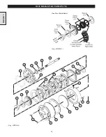
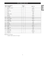
Page 10: ...10 DISC BRAKE PARTS DRAWING Dwg MHP0667 Dwg MHP0630 One Way Clutch Detail Section 1...

Page 11: ...1 11 One way Clutch 1 71044853 12 Pressure Plate 1 24137 13 Friction Plate 5 71126874 14 Separator Plate 6 22033 15 Spacer 2 19007 16 Inner Race 1 24038 17 Outer Race 1 22032 19 Gasket 2 71262257 21 S...

Page 12: ...and a manually operated engagement and release mechanism Dwg MHP1043 Operation The winch operator can engage the brake band at any time whether the winch drum is turning in the haul in direction stati...

Page 13: ...67 105 Spacer 1 23029 106 Brake Bracket 1 21884 107 Capscrew 2 71264832 112 Capscrew 2 71264824 117 Jam Nut 2 71264790 119 Pivot Bar 1 23755 120 Capscrew 1 71288039 129 Locking Pellet 1 23737 130 Caps...

Page 14: ...ustment bolt is a specially treated high strength fastener permanently attached to the jam nut Do not remove the adjustment bolt from the end of the band brake unless the threads have been damaged or...

Page 15: ...essing it out Removal of the larger needle bearing 138 is only required if the bearing housing is cracked or chipped or if the rollers are damaged Removal in this case can be accomplished using a punc...

Page 16: ...t the eccentric shaft bearing surfaces for galling and flat spots 3 Make sure the two bearings in the brake bracket allow the eccentric shaft to move smoothly and easily Replace the bearings if any of...

Page 17: ...bolt at least 10 mm 3 8 inch into the cam plate This ensures that the locking pellet will contact the adjustment bolt and hold it in place Insert the locking pellet inside the threaded hole in the si...

Page 18: ...ver center or if there is excessive resistance reduce the tension by turning the adjustment bolt in the counterclockwise direction There must be slack in the band brake when the handle is in the relea...

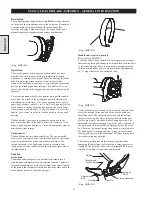
Page 19: ...19 Section 2 SERVICE NOTES...

Page 20: ...20 MANUAL BAND BRAKE PARTS DRAWING 104 120 117 119 103 102 101 105 142 143 130 142 145 137 138 140 141 112 106 107 130 129 131 132 133 134 135 Section 2 Dwg MHP1079...

Page 21: ...117 Jam Nut 2 71264790 119 Pivot Bar 1 23755 120 Capscrew 1 71288039 129 Locking Pellet 1 23737 130 Capscrew 2 52160 131 Cam Plate 1 21893 132 Retainer Ring 1 71145122 133 Washer 1 71137905 134 Sleev...

Page 22: ...y Section 3 Cylinder Cylinder Rod Piston Springs Cover Retainer Dwg MHP0984 B Brake bracket and plunger assembly The brake bracket and plunger assembly is bolted to the drum side of the winch upright...

Page 23: ...ot returning to neutral Refer to the manual for instructions on troubleshooting and adjusting the brake actuation components in the winch control valve The orifice and dump valve assembly are not reli...

Page 24: ...easy access to the band brake assembly 2 Thread a piece of 3 8 NC threaded rod approximately 36 cm 14 inches long fully into the tapped hole in the cylinder rod inside the cylinder Make sure the thre...

Page 25: ...to remove the two socket head capscrews closest to the brake surface The 3 8 inch allen wrench has enough clearance to turn near the drum flange Dwg MHP0979 8 Pull the plunger 114 out of the brake br...

Page 26: ...washer over the threaded rod and then thread a nut all the way down to the cover Tighten the nut until the cover moves far enough to uncover the retainer ring and remove the ring Use a 12 mm approxima...

Page 27: ...ld measure at least 203 mm 8 0 inches long Replace them if they have collapsed or become bent 6 Ensure that the spring 113 has not collapsed or become bent It should measure at least 203 mm 8 0 inches...

Page 28: ...rcise caution can cause mechani cal damage and or injury Dwg MHP0982 4 Insert the piston and cylinder rod assembly into the cylinder and drop the washer 128 into the open end of the piston Dwg MHP0978...

Page 29: ...50 Nm 33 36 ft lbs 3 Gently spread the ends of the brake band and slip it over the flange and onto the brake surface Dwg MHP1099 4 Place the small spring 113 in the end of the plunger and slip the plu...

Page 30: ...one of the lock nuts onto the adjustment bolt so that it holds the adjustment bolt on the brake band with very little slack 10 Loosely thread the adjustment bolt into the plunger 11 Install the rubbe...

Page 31: ...inch from the cylinder cover Tighten the jam nuts closest to the plunger to fasten the adjustment bolt in position Finally remove the 3 8 NC threaded rod from the cylinder rod Dwg MHP0983 Testing the...

Page 32: ...32 AUTOMATIC BAND BRAKE PARTS DRAWING 104 120 119 103 102 101 105 121 122 123 128 124 127 125 126 107 106 112 116 115 117 114 113 108 111 110 109 Dwg MHP1080 Section 3...

Page 33: ...08 Cylinder Rod 1 23885 109 O Ring 1 71049423 110 O Ring 1 52662 111 Retainer Ring 1 54136 112 Capscrew 2 71264824 113 Spring 1 71126643 114 Plunger 1 23886 115 Dowel Pin 1 71144968 116 Roller 1 23883...

Page 34: ...vots on a cross shaft running through an end cap bolted to the valve body The lever is spring loaded so that the control valve returns and automatically locks into the neutral position A clevis attach...

Page 35: ...to common direction control valve symptoms probable causes and remedies Symptom Cause Remedy No drum movement when control valve actuated in Payout direction No air supply Check air lines for rips or...

Page 36: ...andle assembly out of valve cap 450 5 Remove capcrews 439 and 437 and washers 433 from valve cap 450 Using a soft face hammer remove valve cap 450 6 Remove capscrews 418 from shuttle valve body 479 an...

Page 37: ...14 Remove retainer 432 and seperate piston valve 431 from inlet poppet remove O ring 430 from outside of valve piston and O ring 426 from inside of valve piston 15 Seperate poppet seat 428 from inlet...

Page 38: ...ighten to 24 to 30 inch lb 8 9 3 0 Nm Dwg MHP1150 Handle Assembly 1 Apply Loctite 242 on threads of valve handle 449 Screw handle ball 469 onto valve handle 449 and tighten 2 Slide O ring 460 onto val...

Page 39: ...e inlet poppet 7 Slide O ring over inlet poppet and into the groove Press O ring into groove all around and wipe excess Loctite 4212 from poppet surface Allow Loctite 4212 to cure Wear rubber gloves w...

Page 40: ...20 over shaft 401 from the front of the valve body Push into valve body followed by spring 422 16 Slide poppet assembly on to shaft 401 Use fingers to press poppet seat into valve body 17 Install reta...

Page 41: ...ghten capscrews to 54 to 60 inch lbs 20 to 22 Nm NOTICE The slotted pin grooves in the clevis where clevis and shaft 401 are joined make alignment of the cross shaft and clevis difficult To prevent bi...

Page 42: ...g MHP1158 13 Insert capscrews 442 and flatwashers 434 into adapter 440 These capscrews cannot be removed without a Removing end caps or b Removing adapter from valve body 14 Apply Loctite 242 on threa...

Page 43: ...peration Dwg MHP1024 6 Insert capscrew 465 through flatwasher 417 and spring retainer 416 into valve body and tighten 7 Adjusting brake valve 413 Ensure that long portion of sleeve 408 is on the botto...

Page 44: ...65 464 450 448 433 437 446 444 430 431 409 439 445 447 443 460 433 434 442 410 411 424 431 432 438 436 433 439 437 420 417 416 413 421 470 471 Single Air Brake Qty 1 each of Item 412 and Item 413 Dual...

Page 45: ...ndle 1 23747 418 Capscrew 2 71261747 450 Valve Cap 1 23607 419 Gasket 1 23744 460 O Ring 1 71146963 420 Exhaust Poppet 1 23516 461 Cross Shaft 1 23746 421 Plug 1 51897 462 Spring 1 71146948 422 Spring...

Page 46: ...et gears in the second stage which are connected to the planet carrier The planet carrier in the second stage is connected to the outboard upright through the output shaft This prevents planet carrier...

Page 47: ...rbox Removal Section 5 REDUCTION GEAR MAINTENANCE 1 Rotate gearbox until drain plug is in lowest position refer to LUBRICATION Section 2 Drain lubricant into a clean container and observe for particle...

Page 48: ...disassembly check planet gear side clearance 0 005 to 0 032 inches 0 13 to 0 81 mm Spin gears gears should rotate freely If gears are tight or clearance is incorrect disassemble planet assembly Dwg M...

Page 49: ...hers 52 55 and 64 are used in combination to achieve clearance all three might not be present or quantities may vary 4 Tap roll pin 50 out of intermediate planet pin 46 Dwg MHP1187 Inspection 1 Check...

Page 50: ...6 Measure the side clearance and adjust the thrust washers 52 55 or 64 to provide 0 005 0 032 inches 0 13 0 81 mm Spin gears gears should rotate freely Dwg MHP1169 8 Measure the distance that roll pin...

Page 51: ...edle bearings 6 Place another thrust washer on top of assembly Carefully slide assembly right into the output carrier 37 Dwg MHP1161 7 Align the bores and push out the pin tool using the output planet...

Page 52: ...gear 54 followed by thrust washer 63 and then next thrust washer 65 Dwg MHP1163 5 Place retainer ring 53 on end of output sun gear 45 Slide this assembly into intermediate carrier assembly and fasten...

Page 53: ...hrust washer 36 inside of cover 33 use some EP grease to hold in place 14 Align the two threaded holes in cover 33 with the grooves in housing 44 15 Insert capscrews 32 through cover and into housing...

Page 54: ...54 REDUCTION GEAR ASSEMBLY PARTS DRAWING Dwg MHP1221 Section 5...

Page 55: ...ll 3 71113302 67 Bearing Needle 1 71113187 39 Gear Output Planet 3 23893 68 Capscrew 6 71113161 40 Thrust Washer 6 71126478 69 Housing 1 20672 41 Bearing Roller 126 71113286 71 Oil Seal 1 71113179 42...

Page 56: ...r arrangements have been made and written authorization has been provided from the location where the goods were purchased NOTICE Continuing improvement and advancement of design may cause changes to...

Page 57: ...57 SERVICE NOTES...

Page 58: ...58 SERVICE NOTES...

Page 59: ...59 SERVICE NOTES...

Page 60: ...ond B C V7C 5C7 Phone 604 278 0459 Fax 604 278 1254 Latin America Operations Ingersoll Rand Production Equipment Group 730 N W 107 Avenue Suite 300 Miami FL 33172 3107 USA Phone 305 559 0500 Fax 305 5...

Reviews: