background image

Installation and programming manual

1


SmartLevel

SPS24060G

SPS24160G

Power supply station

Installation and programming manual

ISO 9001 Quality Management

certified by BSI with certificate number FM530352

EN 54-4

0051

0051-CPR-0170

0051-CPR-0171

Summary of Contents for SmartLevel SPS24060G

Page 1: ...ramming manual 1 SmartLevel SPS24060G SPS24160G Power supply station Installation and programming manual ISO 9001 Quality Management certified by BSI with certificate number FM530352 EN 54 4 0051 0051 CPR 0170 0051 CPR 0171 ...

Page 2: ...by INIM Electronics This power station must be installed in accordance with the instructions described in this manual and in compliance with the laws in force All power stations from the SmartLevel series are EN54 4 compliant All power stations from the SmartLevel series and all accessory items and special functions have IMQ Sistemi di Sicurezza certification unless otherwise stated Declarations o...

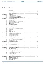
Page 3: ...3 Device management 11 3 1 Product handling and storage 11 3 2 Environmental conditions 11 3 3 Unpacking the device 11 Chapter 4 Functions and features 12 4 1 Controlling the Outputs 12 4 2 Controlling the outputs via the Inputs 13 4 3 How to use the power supply station 13 4 4 Protection circuit 14 Chapter 5 Technical description 15 5 1 Station 15 5 2 Internal devices 16 5 3 Technical specificati...

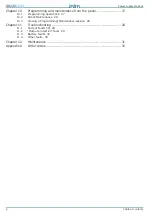
Page 4: ... 27 10 1 Programming operations 27 10 2 Direct Maintenance 28 10 3 Closing a Programming Maintenance session 28 Chapter 11 Troubleshooting 29 11 1 Current faults list 29 11 2 Output protection fault 29 11 3 Battery faults 30 11 4 Other faults 30 Chapter 12 Maintenance 31 Appendix A Order codes 32 ...

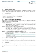
Page 5: ...m It supplies power to remote loads such as fire door magnets sounders emergency signs linear smoke detectors Note The SmartLevel power supply station is EN54 4 compliant and specifically the amendment EN 54 4 1997 A2 2006 which includes a test regarding the internal resistance of the batteries Main features User interface comprising display buttons and buzzer 3 controlled outputs fault relay dire...

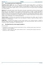
Page 6: ... failure 230V the batteries will take over automatically If the problem persists for a long period thus causing the battery charge to drop below the minimum value required they will be shutdown automatically in order to avoid damage Refer to paragraph 7 6 Connecting the batteries Thermal probe an accessory tool connected to the panel and attached to the battery pack This device monitors the temper...

Page 7: ...hnicians can by means of the necessary tools remove the frontplate of the power supply station They can insert the respective jumpers in order to access and carry out programming and maintenance Processing is inhibited during programming sessions therefore the device will be unable to generate any signals whatsoever Level 4 Technicians employed by the Manufacturer INIM Electronics s r l The manufa...

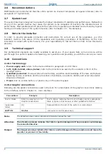
Page 8: ... need 2 10 Conventions 2 10 1 Terminology Power supply unit refers to the device defined in paragraph 2 12 CE Mark Left right behind above below refer to the directions as seen by the operator in front of the mounted device Qualified personnel those persons whose training expertise and knowledge of the laws and bylaws regarding service conditions and the prevention of accidents are able to identif...

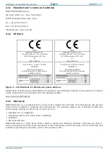
Page 9: ...ucts Improper use that is use for purposes other than those mentioned in this manual will void the warranty For the full details and conditions regarding the warranty refer to the purchase order 0051 INIM ELECTRONICS S R L Via Fosso Antico snc Fraz Centobuchi 63076 Monteprandone AP Italy 08 0051 CPR 0170 EN 54 4 1997 A1 2002 A2 2006 SPS24060G Power supply equipment for fire detection and fire alar...

Page 10: ...atic potential This can be achieved by simply shaking hands Place the board on an anti static surface or a conductor surface with the same potential Further information regarding procedures relating to safety when working with electronic devices can be found in EN 61340 5 1 e CLC TR 61340 5 2 2 14 3 Setting up the system In order to provide adequate protection and instructions for proper use secur...

Page 11: ... must be unpacked with care All waste packaging materials must be disposed of in compliance with the local laws and bylaws in force The metal enclosure of the device is packed carefully inside the cardboard box Note The lead batteries are not included Be sure you have the batteries on hand before starting When you remove the four screws and metal frontplate you will find The SmartLevel motherboard...

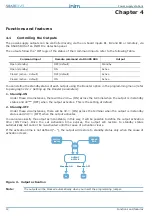
Page 12: ... OFF Under these circumstances there will be 0V ON across the terminal when the output is in standby status and 24V OFF when the output activates You can also classify the output as monostable in this way it will be possible to define the output activation time ON Time Once the set activation time expires the output will restore to standby status automatically but cannot be re activated until the ...

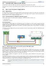
Page 13: ... supply station enclosure The details of fault events can be viewed on the power supply station display The following wiring diagram shows a loop connection using an input output module from INIM Electronics s r l ENEA series Figure 4 Wiring diagram of a loop connection using a EM312SR module Connecting to an RS485 BUS SmartLevel power supply units are equipped with terminals which allow direct co...

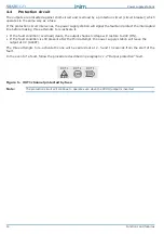
Page 14: ...te it If the fault condition overload clears the output channel voltage will restore to 24V ON If the fault condition is still present after the third attempt the power supply station will leave the output at 0V ALERT The three attempts to re activate the line will be carried out at 2 5 and 10 seconds from the start of the fault In the event of a fault follow the procedure described in paragraph 1...

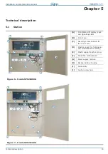
Page 15: ...with display keys and signalling LEDs B Front cover C Securing screw location for the front cover D Plastic support for front panel and motherboard mounting E Plastic support anchor screw F About the motherboard G Power supply module H Backup battery housing I Cable entry J Anchor screw hole B D H G F E I I I J J A C E E E C C C B D I H G F E I I I J J A E E E H C C C C ...

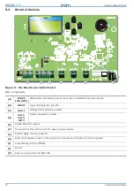
Page 16: ... INPUT Input terminals B1 B2 B3 C FAULT Voltage free fault relay contacts D OUT1 OUT2 OUT3 Output channels terminals E RS485 BUS EOL jumper F Connector for the earth wire of the power supply module G Power supply module connector H Earth fault bypass jumper if the jumper is removed earth faults will not be signaled I Programming jumper PROG J Buzzer K Reserved connectors DO NOT USE A B D D D E C F...

Page 17: ...ximum output current 2 1 A 5 2 A Imax a 1 5 A 4 A Imax b 1 5 A 4 A Maximum battery current emission during primary power failure 1 5 A 4 A Maximum current for external loads and accessory devices 1 46 A 3 96 A Maximum battery charge current 0 6 A 1 2 A Minimum current Imin 40 mA Battery specifications 2 x 12V 7 Ah 2 x 12V 17 Ah 2 x 12 V 7 Ah YUASA NP 12 FR or similar with case flame class UL94 V2 ...

Page 18: ...ent To view the restored fault condition details consult the events log using the main menu level 1 To restore the fault memory return to LED Off status reset the control panel level 2 D CPU FAULT yellow Indicates that the control panel CPU is not operating properly The power supply station must be returned to the manufacturer for repair Indicates that the CPU has re initialized due to control pan...

Page 19: ...losure securely to the wall 7 2 RS485 BUS wiring Figure 11 Connecting the RS485 BUS 1 Use a 4 pole shielded twisted cable 2 The cable length between the INIM panel and the SmartLevel power supply station must not exceed 1000m 3 Connect one end of the cable shield to the control panel earth terminal Note The terminals of the SmartLevel power supply module are isolated electrically from the RS485 BU...

Page 20: ...electronic are suitable for SELV circuitry only 7 5 Connecting the mains power source The power system of the SmartLevel stations is EN54 4 compliant Danger DO NOT power up the system with a non compliant voltage 1 Connect the mains power supply to the terminals on the power supply module Figure 9 Switching power supply A and Figure 13 Earthing system A For a safety standards compliant system the ...

Page 21: ...tion device fuse and disconnect the power supply 5 Ensure that low current safety or signal lines DO NOT come into contact with points with potentially dangerous currents Using a plastic cable tie bunch the wires together and secure them to one of the wire hooks on the backplate of the enclosure G Note The connection wires to the electrical mains and also any other wires inside the cabinet must be...

Page 22: ... station tests the battery efficiency every 10 minutes If their internal resistance is over the allowed limit the event will be indicated Batt fault on the display according to the amendment EN54 4 1997 A2 Battery level test The battery test circuit monitors the battery status efficiency and charge continuously In the event of mains failure the power supply station will still monitor the battery v...

Page 23: ... charging process in accordance with the battery temperature The thermal probe protects against battery overheating and consequent permanent damage 7 7 1 Connecting the thermal probe Connect the thermal probe to the proper connector of the power supply module Figure 9 Switching power supply D and Figure 14 Connecting the batteries D Using adhesive insulating tape attach the thermal probe to one of...

Page 24: ...nd the FAULT LED will go On solid When the fault clears the LED will blink to indi cate that the fault has been saved to the memory 4 Check for the presence of faults If the fault persists check all wiring sections thoroughly refer to Chapter 11 Troubleshooting 5 Clear all fault events 6 Access the main menu refer to Chapter 9 Viewing the display screens and using the scroll keys select Reset stat...

Page 25: ...3 Electrical current value indicates the realtime electrical current value of each output Electrical current and voltage values indicates the total realtime electrical current value of the outputs the sum of the electrical currents of the 3 outputs and the realtime voltage on the outputs Output status indicates the ON OFF or Alert status protection active of each output Output status Description O...

Page 26: ...y settings restore to default Output status Activation Restoral of all faults events 9 3 3 Resetting the power supply station From station Ok Reset Ok The power supply station will reset when you press Ok Note The successive options on the Main menu are available only when the PROG jumper is inserted 9 3 4 Maintenance From station Ok Maintenance Ok This option will allow you to access the maintena...

Page 27: ...le in paragraph 4 1 Controlling the Outputs it will be at 24V activation value 0V Standby OFF When the output is in standby status refer to the table in paragraph 4 1 Controlling the Outputs it will be at 0V activation value 24V Activation Time Using keys S and T this programming field will allow you to select an output and define its activation time duration The maximum time is 20 minutes You can...

Page 28: ...the desired field then press Ok to modify the value Press Esc to save the setting and exit 10 2 2 Booster ON OFF From station Ok Maintenance Ok Booster ON OFF Ok This section will allow you to modify the output channels directly and view the status of the circuit breakers Using keys S and T select the desired output then adjust it to requirements using the Ok key If the selected output is set as O...

Page 29: ...nu 1 Insert the PROG Jumper 2 From station Ok Maintenance Ok Booster ON OFF Ok the power supply station will reset the Fault LED and the Fault relay 3 Set the protected output to OFF 4 Clear the fault on the output circuit in question 5 Set the protected output to ON and wait until the power supply station restores the output automatically If the condition persists for more than 10 15 seconds repe...

Page 30: ...fault has cleared 4 If both batteries have a voltage of 12 5 13 V it means they are both inefficient even though the voltage without load is correct Replace both batteries Allow them to charge for several hours Check that the fault has cleared 11 3 2 Low Battery The batteries are running low This signal should be present only during primary power source failure Mains 230 V Mains power must be rest...

Page 31: ...f cleaning product or solvent 2 From station press Ok LED test Ok to check the proper operating capability of the LEDs and buzzer 3 Check the battery efficiency and change them if necessary 4 Check the integrity of all wires and connections 5 Ensure that there are no extraneous objects inside the control panel Note Points 1 and 2 can be carried out by authorized persons whereas all other points mu...

Page 32: ...imization SPS24060G 60W 27 6V SmartLevel power supply station in metal enclosure with 3 controlled outputs fault relay and connection to RS485 BUS SPS24060S 60W 27 6V SmartLevel power supply station in metal enclosure with 1 controlled output 2 fault relays and connection to the loop SPS24160G 160W 27 6V SmartLevel power supply station in metal enclosure with 3 controlled outputs fault relay and c...

Page 33: ...Installation and programming manual 33 ...

Page 34: ...osso Antico snc fraz Centobuchi 63076 Monteprandone AP ITALY Tel 39 0735 705007 _ Fax 39 0735 704912 info inim biz _ www inim biz ISO 9001 Quality Management certified by BSI with certificate number FM530352 ...

Reviews: