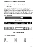
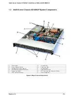
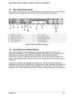
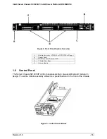
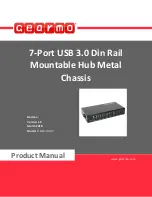
background image


Intel

®

 Server Chassis SC1400UP / 

Intel

®

 Server Platform SR1425BK1-E 


Technical Product Specification 

Intel order number C94051-001 


Revision 1.0

October 2004

Enterprise Platforms and Services Marketing

Summary of Contents for SC1400UP

Page 1: ...Intel Server Chassis SC1400UP Intel Server Platform SR1425BK1 E Technical Product Specification Intel order number C94051 001 Revision 1 0 October 2004 Enterprise Platforms and Services Marketing...

Page 2: ...ifications February 2004 0 5 Updated to reflect Alpha first external release July 2004 0 8 Added CPU air duct updated SATA and SCSI backplane info added LCP info added riser card info October 2004 0 9...

Page 3: ...ot finalize a design with this information Revised information will be published when the product is available Verify with your local sales office that you have the latest datasheet before finalizing...

Page 4: ...ry Air Duct and Side Air Baffle 22 2 4 Hard Drive Bays 23 3 Peripheral and Hard Drive Support 24 3 1 Slimline Drive Bay 24 3 1 1 Floppy Drive Support with or without Backplane present 24 3 2 Hard Disk...

Page 5: ...nector 52 6 5 2 P2 Processor Power Connector 53 6 5 3 P3 P5 Peripheral Connectors 53 6 6 AC Inlet Connector 54 6 7 Marking and Identification 54 6 8 AC Input Voltage 54 6 9 AC Line Transient Specifica...

Page 6: ...6 31 Residual Voltage Immunity in Standby mode 63 6 32 Protection Circuits 63 6 33 Current Limit OCP 63 6 34 Over Voltage Protection OVP 64 6 35 Over Temperature Protection OTP 64 6 36 Control and In...

Page 7: ...9 1 Certification Conditions 72 7 19 2 Isolation Between Primary Secondary 72 7 19 3 Creepage Clearance Requirements 72 7 19 4 Leakage Current Maximums 72 7 19 5 Max Surface Temperatures 72 7 19 6 Dat...

Page 8: ...an EMC Compatibility 78 9 2 6 BSMI Taiwan 78 9 3 Replacing the Back up Battery 78 9 4 System Level Environmental Limits 79 9 5 Serviceability 80 Appendix A Intel Server Chassis SC1400UP Integration an...

Page 9: ...e Configuration 25 Figure 17 Hard Drive Tray Assembly 28 Figure 18 Drive Tray with Drive Blank 29 Figure 19 Hot Swap SCSI Backplane Layout 30 Figure 20 Hot Swap SCSI Backplane Functional Diagram 30 Fi...

Page 10: ...Revision 1 0 x Figure 36 Output Voltage Timing 62 Figure 37 Turn On Off Timing Power Supply Signals 63 Figure 38 PSON Required Signal Characteristic 65 Figure 39 SE7221BK1 E Board Layout 75...

Page 11: ...nnector Pinout J2 J3 J4 J5 J6 41 Table 14 22 Pin SATA Connector Pinout 41 Table 15 Contol Button and Intrusion Switch Functions 43 Table 16 Control Panel LED Functions 43 Table 17 SSI Power LED Operat...

Page 12: ...ing 62 Table 39 Over Current Protection OCP 64 Table 40 Over Voltage Protection OVP Limits 64 Table 41 PSON Signal Characteristic 65 Table 42 PWOK Signal Characteristics 66 Table 43 Harmonic Limits Cl...

Page 13: ...ly available as an integrated system as the SR1425BK1 E Both the board and chassis have a feature set that is designed to support the high density server market This document provides details on the c...

Page 14: ...ts A Power supply G Control Panel B Chassis Intrusion Switch H Hard Drive Bays C Full length PCI Add in card slot I Chassis Handle D PCI Riser Card Assembly Placement J Slim Line Drive Bay E System Fa...

Page 15: ...heral Bays The Server Chassis SC1400UP is designed to support several different hard drive and peripheral configurations The hard drive bay is designed to support up to three cabled SATA or SCSI drive...

Page 16: ...ay CDROM or DVD CDR or Floppy B Control Panel C Hard Drive Fault Activity LED D 1 Hard Drive Bays E Chassis Handle 1 6 Control Panel The Server Chassis SC1400UP control panel assembly is pre assembled...

Page 17: ...stem Status LED K Recessed NMI Button Tool Required F Hard Drive Activity LED L Video connector not supported on SC1400UP 1 7 Power Sub system The power sub system of the SC1400UP consists of a single...

Page 18: ...ck attach point 1 10 Rack and Cabinet Mounting Options The SC1400UP chassis was designed to support 19 wide by up to 24 30 deep server cabinets The chassis can be configured to support either a relay...

Page 19: ...400UP Intel Server Platform SR1425BK1 E Revision 1 0 19 Light pipes in the front bezel supporting the Standard Control Panel allow the system status LEDs to be monitored with the bezel installed Figur...

Page 20: ...oling and airflow to the system A fan on the processor heat sink is not necessary in this chassis In order to maintain the necessary airflow within the system the air baffle CPU Memory air duct and th...

Page 21: ...nstallation and serviceability of the server chassis cooling subsystem The individual fans are not hot swappable The server must be turned off and power removed from the system before any of the fans...

Page 22: ...he rotational speed for all the fans within fan module Note There is no fan redundancy Should a fan fail the system should be shut down as soon as possible to have the fan replaced The system fans are...

Page 23: ...cannot be installed if the air damn is in place and two processors are installed Figure 13 CPU Memory Air Duct Note If the CPU Memory air duct is removed the system will not meet the thermal cooling...

Page 24: ...100pin connector on the SATA and SCSI backplane DOES NOT APPLY to the Intel Server Chassis SC1400UP and Intel Server Board SE7221BK1 E Drives are mounted on a tool less tray which allows for easy inst...

Page 25: ...D 7 8 FD_INDEX_L GND 9 10 FD_MTR0_L GND 11 12 FD_DS1_L GND 13 14 FD_DS0_L GND 15 16 FD_MTR1_L Unused 17 18 FD_DIR_L GND 19 20 FD_STEP_L GND 21 22 FD_WDATA_L GND 23 24 FD_WGATE_L GND 25 26 FD_TRK0_L Un...

Page 26: ...E_SDD 4 13 14 IDE_SDD 12 IDE_SDD 3 15 16 IDE_SDD 13 IDE_SDD 2 17 18 IDE_SDD 14 IDE_SDD 1 19 20 IDE_SDD 15 IDE_SDD 0 21 22 IDE_SDDREQ GND 23 24 IDE_SDIOR_L IDE_SDIOW_L 25 26 GND IDE_SIORDY 27 28 IDE_SD...

Page 27: ...6 GND IDE_SIORDY 27 28 IDEP_ALE_H IDE_SDDACK_L 29 30 GND IDE_IDE_S 31 32 NC_IDEIO16_L IDE_SDA 1 33 34 IDE_CBL_DET_S IDE_SDA 0 35 36 IDE_SDA 2 IDE_SDCS0_L 37 38 IDE_SDCS1_L IDE_SEC_HD_ACT_L 39 40 GND 3...

Page 28: ...ote Depending on the controller used SATA hard disk drives may not report errors using the drive s status indicator OM11684 C E A B D Figure 17 Hard Drive Tray Assembly A Hard Drive B Drive Carrier C...

Page 29: ...ce with SCSI Accessed Fault Tolerant Enclosures SAF TE specification version 1 00 and addendum o Compliance with Intelligent Platform Management Interface IPMI Support for up to three U320 LVD SCSI Dr...

Page 30: ...chitectural blocks of the SC1400UP 1U SCSI HSBP The following figure shows the functional blocks of the hot swap SCSI backplane Figure 20 Hot Swap SCSI Backplane Functional Diagram SCSI Connector to S...

Page 31: ...1 1 SCSI Interface The GEM359 supports LVD SCSI operation through 8 bit asynchronous SCSI data transfers The following SCSI Command Set is supported Inquiry Read Buffer Write Buffer Test Unit Ready Re...

Page 32: ...l 24C02 or equivalent serial EEPROM for storing the FRU information The 24C02 provides 2048 bits of serial electrically erasable and programmable read only 3 3 2 1 5 External Memory Device SC1400UP 1U...

Page 33: ...llowing table shows the power connector pinout Table 8 SCSI Backplane Power Connector Pinout J1 Pin Name Pin Name 1 GND 4 P12V 2 GND 5 P12V 3 P5V 6 P5V_STBY 3 3 3 2 SCSI Connector Backplane to SCSI ad...

Page 34: ...STP A25 B25 BP_SCSI_RSTN BP_SCSI_MSGP A26 B26 BP_SCSI_MSGN BP_SCSI_SELP A27 B27 BP_SCSI_SELN BP_SCSI_CDP A28 B28 BP_SCSI_CDN BP_SCSI_REQP A29 B29 BP_SCSI_REQN BP_SCSI_IOP A30 B30 BP_SCSI_ION BP_SCSI_D...

Page 35: ..._MSGP 55 15 BP_SCSI_MSGN BP_SCSI_RSTP 56 16 BP_SCSI_RSTN BP_SCSI_ACKP 57 17 BP_SCSI_ACKN BP_SCSI_BSYP 58 18 BP_SCSI_BSYN BP_SCSI_ATNP 59 19 BP_SCSI_ATNN BP_SCSI_DP0P 60 20 BP_SCSI_DP0N BP_SCSI_D7P 61...

Page 36: ...s o SATA and SATA II extension compatible o Compliance with SATA Accessed Fault Tolerant Enclosures SAF TE specification version 1 00 and addendum o Compliance with Intelligent Platform Management Int...

Page 37: ...of the board Figure 24 SATA Backplane Layout Figure 25 SATA Backplane Layout 3 4 2 SATA Backplane Functional Architecture This section provides a high level description of the functionality distribut...

Page 38: ...s in band SAF TE management through the SATA Host I2 C interface The GEM424 comes in a 80 pin Thin Quad Flat Pack TQFP package and operates from 3 3V and input clock frequency of 20MHz It has general...

Page 39: ...rver Chassis SC1400UP 1U SATA HSBP I2C Bus Connection Diagram 3 4 2 1 3 Temp Sensor SC1400UP 1U SATA HSBP provides National LM75 or equivalent temperature sensor with over temperature detector The hos...

Page 40: ...tion GREEN ON HDD Activity AMBER ON HDD Fail AMBER Blinking Rebuild in progress 3 4 3 SATA Backplane Connector Definitions 3 4 3 1 Power Connector The SATA backplane provides power for up to three ATA...

Page 41: ...5 SCSI 5V GND 4 16 SCSI 5V DRV_TX_P 5 17 GND DRV_TX_N 6 18 Unused GND 7 19 GND P3V3 8 20 SCSI 12V P3V3 9 21 SCSI 12V P3V3 10 22 SCSI 12V GND 11 23 GND GND 12 24 GND 3 4 3 4 Slim line Floppy Drive Conn...

Page 42: ...ontrol panel assembly module slides into a predefined slot on the front of the chassis Once installed communication to the baseboard can be achieved by either attaching a 50 pin cable to a hot swap ba...

Page 43: ...able interrupt After issuing the interrupt a memory download can be performed to determine the cause of the problem 4 2 Control Panel LED Indicators The control panel houses six LEDs which are viewabl...

Page 44: ...is off due to a failure or configuration change that prevents the BIOS from running The current limiting resistors for the power LED the system fault LED and the NIC LEDs are located on the server bo...

Page 45: ...perature voltage or fan non critical threshold crossing Chassis intrusion Satellite controller sends a non critical state via the Set Fault Indication command to the BMC Set Fault Indication command f...

Page 46: ...switched between the two with the control panel having priority over the rear video This provides for easy front accessibility to the server 4 4 Internal Control Panel Assembly Headers The Control Pa...

Page 47: ...19 NIC2_ACT_LED_L GND 22 21 BP_I2C_5V_SDA FP_ID_SW_L 24 23 BP_I2C_5V_SCL NIC1_ACT_LED_L 26 25 FP_CHASSIS_L FP_NMI_BTN_L 28 27 NIC1_LINK_LED_R_L EMP_DSR2_L 30 29 GND EMP_SIN2 32 31 EMP_INUSE_L EMP_RTS2...

Page 48: ...he bracket A third is used to secure the add in card to the riser Tabs on the rear of the riser bracket allow the riser card to safely mate with the chassis even when no riser card is installed Note E...

Page 49: ...l Server Chassis SC1400UP Intel Server Platform SR1425BK1 E Revision 1 0 49 Figure 32 1U Full Height PCI X Riser Card Mechanical Drawing Figure 33 1U Full Height PCI Express Riser Card Mechanical Draw...

Page 50: ...tor fits into a 1U system and provides a wire harness output to the system An IEC connector is provided on the external face for AC input to the power supply The power supply provides two non redundan...

Page 51: ...ressure in H 2 O Figure 35 Airflow Characteristics 6 3 Acoustics The power supply provides cooling to both the supply and partially to the system To meet minimum system requirement the power supply li...

Page 52: ...supply with exception to the air exhaust side must be classified as Handle knobs grips etc held for short periods of time only 6 5 Output Connectors Listed or recognized component appliance wiring mat...

Page 53: ...2 6 5 2 P2 Processor Power Connector Connector housing 4 Pin Molex 39 01 3042 or equivalent Contact Molex 44476 1111 or equivalent Table 25 P2 Processor Power Connector PIN SIGNAL 18 AWG COLOR PIN SIG...

Page 54: ...nput voltage below 85VAC shall not cause damage to the power supply including a fuse blow Table 27 AC Input Rating PARAMETER MIN RATED MAX Voltage 110 90 Vrms 100 127 Vrms 132 Vrms Voltage 220 180 Vrm...

Page 55: ...owed provided the function is self recoverable or can be restored by the operation of the controls 6 10 1 Electrostatic Discharge Susceptibility The power supply complies with the limits defined in EN...

Page 56: ...AC dropout requirement over rated AC voltages frequencies and 75 maximum output loading 225W conditions Any dropout of the AC line shall not cause damage to the power supply The power supply shall hol...

Page 57: ...test voltage should be used In addition the insulation system must comply with reinforced insulation per safety standard IEC 950 Separation between the primary and secondary circuits and primary to gr...

Page 58: ...ing the remote sense to the output voltage internal to the power supply Remote sense must be able to regulate out a minimum of 200mV drop on the 3 3V output The remote sense return ReturnS must be abl...

Page 59: ...ges must stay within the following voltage limits when operating at steady state and dynamic loading conditions These limits include the peak peak ripple noise All outputs are measured with reference...

Page 60: ...500 2200 F 12V 1 350 F 5VSB 20 350 F 6 25 Closed loop stability The power supply shall be unconditionally stable under all line load transient load conditions including capacitive load ranges A minimu...

Page 61: ...e failure in the primary side of one power supply doesn t cause the other to shut down 6 30 Timing Requirements These are the timing requirements for the power supply operation The output voltages mus...

Page 62: ...rom PSON active to output voltages within regulation limits 5 400 msec T pson_pwok Delay from PSON deactive to PWOK being de asserted 50 msec Tpwok_on Delay from output voltages within regulation limi...

Page 63: ...outputs to shutdown If the power supply latches off due to a protection circuit tripping an AC cycle OFF for 15sec and a PSON cycle HIGH for 1sec shall be able to reset the power supply 6 33 Current L...

Page 64: ...at the power pins of the power supply connector Exception 5VSB rail should be able recover after its over voltage condition occurs Table 40 Over Voltage Protection OVP Limits Output Voltage MIN V MAX...

Page 65: ...m the system Pull up to VSB located in power supply PSON Low ON PSON High or Open OFF MIN MAX Logic level low power supply ON 0V 1 0V Logic level high power supply OFF 2 0V 5 25V Source current Vpson...

Page 66: ...T pwok_off 1ms 200msec 6 39 Environmental Requirements 6 40 Temperature Operating Ambient normal mode inlet air 0 C min 45C max at 1800 meter above sea level At full load with a maximum rate of change...

Page 67: ...er axis for 3 axis on all samples 6 45 Thermal Shock Shipping Non operating 40 C to 70 C 50 cycles 30 C min transition time 15 C min duration of exposure to temperature extremes for each half cycle sh...

Page 68: ...the requirements of EN61000 3 2 Class A and the Guidelines for the Suppression of Harmonics in Appliances and General Use Equipment Class A for harmonic line current content at full rated power See T...

Page 69: ...mperature During abnormal conditions such as a short circuit and the like no de rating is allowed as long as each component max rating is not exceeded Any exceptions are subject to final approval 7 7...

Page 70: ...hough a power supply can be designed for worldwide compliance there may be cost factors that drive different versions of supplies for different geographically targeted markets 7 14 Power Supplies Comp...

Page 71: ...ollowing particular standards a EN 61000 4 2 Electrostatic Discharge b EN 61000 4 3 Radiated RFI Immunity c EN 61000 4 4 Electrical Fast Transients d EN 61000 4 5 Electrical Surge e EN 61000 4 6 RF Co...

Page 72: ...flame retardant e g brominated flame retardants 7 19 Other Safety Requirement Notations 240VA Limited Circuits All secondary circuits shall be evaluated as operator accessible circuits This means the...

Page 73: ...tings Power supply shall be tested to allow Nominal AC input operating voltages 100 127 VAC and 200 240 VAC and current rating 127V is required for countries such as Mexico The earth safety conductor...

Page 74: ...Controllers NICs On board platform instrumentation using a National PC87431M mini BMC External IO connectors Stacked PS2 ports for keyboard and mouse RJ45 Serial B Port Two RJ45 NIC connectors 15 pin...

Page 75: ...t M DIMM Sockets DIMM_1A DIMM_2A X SATA 2 Connector C PCI X 64 100 Slot N Front USB Header optional Y SATA 1 Connector D PCI X 64 100 Slot O System Fan Headers 5 6 7 8 Z BIOS Control Jumper E Intel Ad...

Page 76: ...ive FCC Class A Verification Radiated Conducted Emissions USA ICES 003 Class A Radiated Conducted Emissions Canada CISPR 22 Class A Radiated Conducted Emissions International EN55022 Class A Radiated...

Page 77: ...encouraged to try to correct the interference by one or more of the following measures Reorient or relocate the receiving antenna Increase the separation between the equipment and the receiver Connec...

Page 78: ...ance too and complies with the Low Voltage Directive 73 23 EEC and EMC Directive 89 336 EEC The product has been marked with the CE Mark to illustrate its compliance 9 2 5 Japan EMC Compatibility Elec...

Page 79: ...ren VARNING Explosionsfara vid felaktigt batteribyte Anv nd samma batterityp eller en ekvivalent typ som rekommenderas av apparattillverkaren Kassera anv nt batteri enligt fabrikantens instruktion VAR...

Page 80: ...ced by qualified technical personnel only The desired Mean Time To Repair MTTR of the system is 30 minutes including diagnosis of the system problem To meet this goal the system enclosure and hardware...

Page 81: ...not needed in the server chassis SC1400UP The fan pack power supply fans and passive processor heatsink provide the necessary cooling needed for the system Using a processor fan in this chassis may ca...

Page 82: ...anagement Port FP Front Panel FRB Fault Resilient Boot FRU Field Replaceable Unit LPC Low Pin Count MTBF Mean Time Between Failure MTTR Mean Time to Repair OTP Over Temperature Protection OVP Over Vol...

Reviews: