
*D
13
31
7-
00
1*
D
13
31
7-
00
1
Intel® Server Board Guide
Intel® Server Board
Product Code
SE7230NH1-E
SE7320EP2, SE7520BD2
SE7525RP2
SE7320EP2, SE7520BD2
SC5295UP
SC5295DP
SC5295WS
SC5295BRP
Tools Required
Anti-static
wrist strap
Phillips*
screwdriver
Caution
Observe normal ESD
(Electrostatic Discharge)
procedures during
system integration to avoid
possible damage to server board
and/or other components.
Installation and service
of this product to be
performed only by
qualified service personnel to
avoid risk of injury from
electrical shock or energy hazard.
Warning
Warning
Read all caution and safety statements in this document before performing any of the instructions. Also see the
Intel
®
Server Board and Server
Chassis Safety Information
document at:
http://support.intel.com/support/motherboards/server/sb/cs-010770.htm
for complete safety information.
Thank you for buying the Intel
®
Entry Server Chassis SC5295-E.
The following information will help you to prepare your chassis
for integration with your selected Intel
®
Server Board.
These guides and other supporting documents (including
a list of supported server boards) are located on the web at
http://support.intel.com/support/motherboards/server
.
If you are not familiar with ESD (Electrostatic Discharge) procedures used during system
integration, please see the Intel
®
Entry Server Chassis SC5295-E User Guide, available on
the CD or at
http://support.intel.com/go/serverbuilder.
Intel
®
Entry Server Chassis SC5295-E
UP/DP/WS/BRP
Quick Start User's Guide
Building Value With Intel
Server Products, Programs and Support
Get the high-value server solutions you need by
taking advantage of the outstanding value Intel
provides to system integrators:
• High-quality server building blocks
• Extensive breadth of server building blocks
• Solutions and tools to enable e-Business
• Intel
®
Server Management
• Comprehensive training services
• Worldwide 24x7 technical support
[AT&T Country Code + 866-655-6565]
1
• World-class service, including a three-year
limited warranty and Advanced Warranty
Replacement
1
• Product information, including product
briefs and technical product
specifications
• Sales tools, such as videos and
presentations
• Training information, such as the Intel
®
Online Learning Center
• Support Information and much more
Intel
®
ServerBuilder is your one-stop shop
for information about all of Intel's Server
Building Blocks such as:
For more information on Intel's added-value
server offerings, visit the Intel
®
ServerBuilder
website at:
www.intel.com/go/serverbuilder
1
Available only to Intel
®
Channel Program
Members, part of the Intel
®
e-Business Network.
P
re
li
m
in
ar
y
D
ra
ft
Intel is a registered trademark of Intel Corporation or its subsidiaries in the United States and other countries. * Other names and brands may be claimed as the property of others. Copyright © 2005, Intel Corporation. All rights reserved.
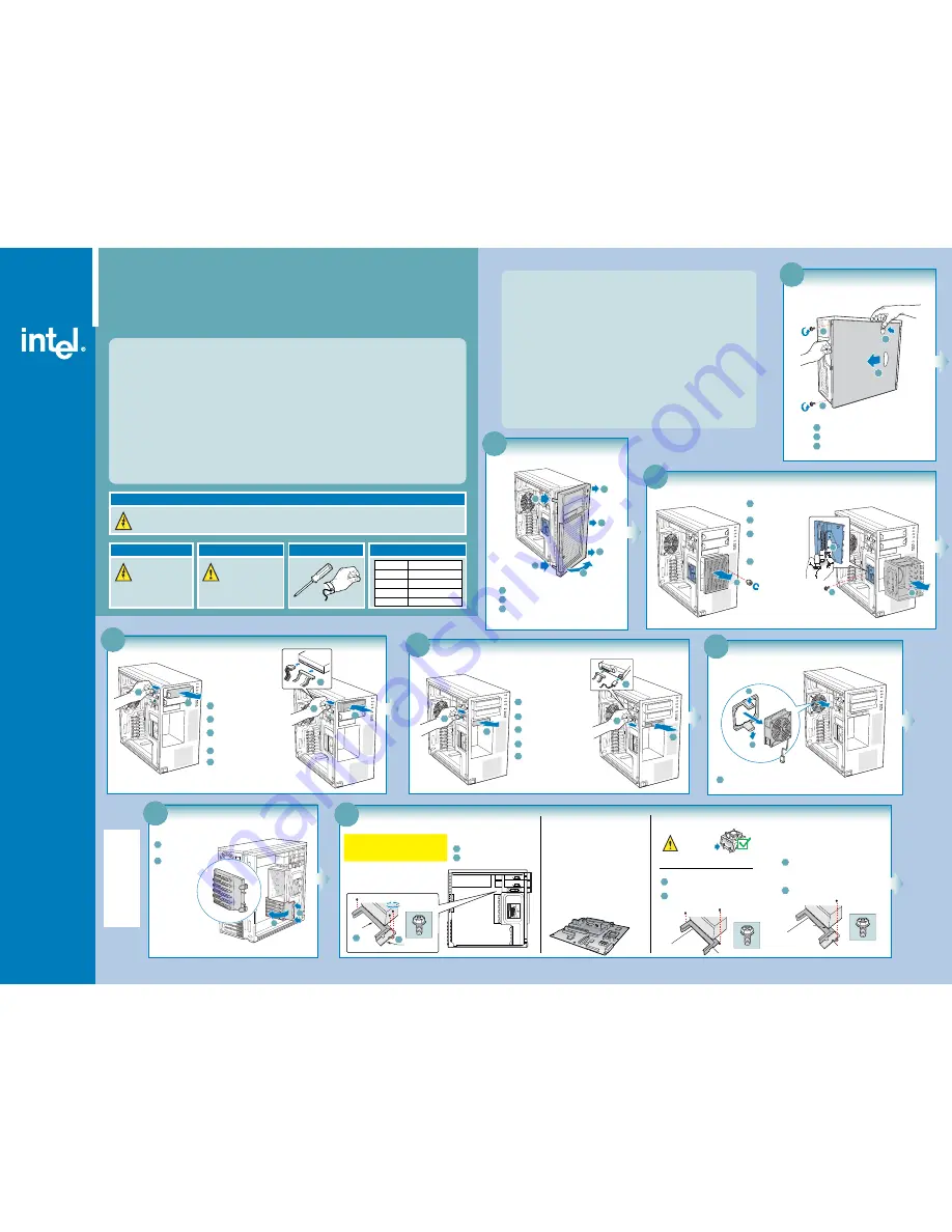
8
Install Server Board
Large
Duct
Note: Save these
screws.
Small Duct
1
2
Server
Board
Tab
engages
here
Remove the small duct (one screw).
1
Remove the large duct (two screws).
2
Part A: Remove CPU Ducts
Note: The SC5295UP version of the Entry Server Chassis
SC5295-E does NOT have any CPU ducts to remove or
install. You will only need to remove and install CPU ducts
IF you have a SC5295DP, SC5295WS, or SC5295BRP.
Note: The CPU ducts must be removed prior to
installing the server board.
Part B: Install Server Board
Open the Intel
®
Server Board box. Follow the
instructions in the enclosed Intel
®
Server
Board Quick Start User's Guide and return
to this document when finished.
Use the mounting screws, bumpers and
standoffs (if necessary) that came with your
chassis to secure the server board to
the chassis.
See your Intel® Server Board Quick Start
User's Guide for server board installation
instructions and installation of the back panel
I/O shield.
Part C: Install CPU Ducts
Lower the large CPU duct into chassis and line
up with two mounting holes in chassis.
Note: Tab on small CPU duct must engage
corresponding opening in large CPU duct.
3
Lower the small CPU duct into chassis and line
up with mounting hole in chassis.
4
Attach to chassis using the single screw you
saved from Part A.
1
Attach to chassis using the two screws you saved
from Part A.
2
Only required for Intel
®
Server Boards
SE7320EP2 and SE7525RP2:
DO NOT USE with a Passive Thermal Solution or the
Intel
®
Workstation Cooling Kit.
This duct should only
be used with Active
Thermal Solutions.
7
Remove PCI Card Guide
1
2
Press in on two blue
tabs.
1
Pull PCI Card Guide
outward and
remove from
chassis.
2
6
Remove System Fan
1
1
Press two bracket tabs outward and remove
system fan.
1
5
Install Floppy Drive
3
4
1
2
5
3
Insert floppy drive into Device Bay
until it is in position.
2
Move latch to "unlock" position.
1
Remove the EMI Shield from
the 3.5-in Device Drive Bay.
5
Connect power and data cables to
the rear of the floppy drive.
4
Move latch to the "lock" position.
4
Install CD-ROM or DVD-ROM Drive
3
4
1
2
5
3
Insert CD-ROM or DVD-ROM drive
into Device Drive Bay until it is
in position.
2
Move latch to the "unlock" position.
1
Remove the EMI Shield from the
5.25-in Device Drive Bay.
5
Connect power and data cables to
the rear of the CD-ROM or DVD-ROM
drive.
4
Move latch to the "lock" position.
3
Remove Hard Drive Cage
4
3
2
1
3
Push the blue plastic
release mechanism
upward to unlatch the
hard drive cage.
2
Remove shipping screw.
1
Loosen thumb screw and remove
hard drive cage EMI shield.
Once released, pull the
hard drive cage out of the
chassis.
4
2
Remove Front Bezel Assembly
3
Disengage three bezel clips that attach the right side
of the bezel to the right side of the chassis and remove.
2
Rotate left side of front bezel assembly outward slightly.
1
Disengage two bezel tabs from leftside of chassis.
2
3
1
1
3
3
1
Remove Side Cover
1
2
Remove two shipping screws.
Push in latch.
3
Slide side cover rearward and remove.
2
3
1
1


