background image

CARBON MONOXIDE POISONING AND FIRE

HAZARD
Failure to follow this warning could result in

personal injury, death, and/or property dam-

age.
This furnace is not designed for use in mobile

homes, trailers or recreational vehicles.

!

ELECTRIC SHOCK HAZARD
Failure to follow this warning

could result in injury and/or

death.
Turn OFF all power, lockout and

tag with suitable warning label

before servicing.

!

International Comfort Products, LLC

Lewisburg, TN 37091 U.S.A.

See section 5 for Category 

I

 definition.

INSTALLER: Affix these instructions

on or adjacent to the furnace.

CONSUMER: Retain these 

instructions for future reference.

Portions of the text and tables are reprinted from ANSI Z223.1/NFPA 54

!

2009

, with permission of National Fire Protection Association, Quincy, MA 02269 and American Gas Association, Wash-

ington, DC 20001.  This reprinted material is not the complete and official position of the NFPA or ANSI, on the referenced subject, which is represented only  by the standard in its entirety.

WARNING

WARNING

WARNING

* Denotes Brands (C, H, T)

Printed in U.S.A.

441 01 2613 05  

Sept. 2009

80+ SINGLE STAGE GAS FURNACE

Category I Furnace

N8MPN/N8MPL & *8MPN/*8MPL

Upflow/Downflow/Horizontal

SAFETY CONSIDERATIONS

Improper installation, adjustment, alteration, service, maintenance, or use can cause explosion, fire, electrical shock, or other conditions

which may cause death, personal injury, or property damage. Consult a qualified installer, service agency, or your distributor or branch for

information or assistance. The qualified installer or agency must use factory

!

authorized kits or accessories when modifying this product.

Refer to the individual instructions packaged with the kits or accessories when installing.
Follow all safety codes. Wear safety glasses, protective clothing, and work gloves. Use quenching cloth for brazing operations. Have fire

extinguisher available. Read these instructions thoroughly and follow all warnings or cautions included in literature and  attached to the unit.

Consult local building codes, the current editions of the National Fuel Gas Code (NFCG) NFPA 54/ANSI Z223.1, National Electrical Code

(NEC) NFPA 70.
In Canada refer to the current editions of the National standards of Canada CAN/CSA

!

B149.1 and .2 Natural Gas and Propane Installation

Codes, and Canadian Electrical Code CSA C22.1.

Recognize safety information. This is the safety

!

alert symbol 

. When you see this symbol on the unit and in instructions or manuals, be

alert to the potential for personal injury.  Understand these signal words; DANGER, WARNING, and CAUTION. These words are used with

the  safety

!

alert  symbol.  DANGER  identifies  the  most  serious  hazards  which 

will 

result  in  severe  personal  injury  or  death.  WARNING

signifies hazards which 

could 

result in personal injury or death. CAUTION is used to identify unsafe practices which 

may 

result in minor

personal injury or product and property damage. NOTE is used to highlight suggestions which 

will

 result in enhanced installation, reliability,

or operation.

Table of Contents

1. Safe  Installation Requirements

3

. . . . . . . . . . . . . . . . 

2.  Installation

4

. . . . . . . . . . . . . . . . . . . . . . . . . . . . . . . . 

3.  Side Venting

8

. . . . . . . . . . . . . . . . . . . . . . . . . . . . . . . 

4.  Combustion & Ventilation Air

9

. . . . . . . . . . . . . . . . . . 

5.  Gas Vent Installation

12

. . . . . . . . . . . . . . . . . . . . . . . . 

6.  Horizontal Venting

13

. . . . . . . . . . . . . . . . . . . . . . . . . 

7.  Masonry Chimney Venting

15

. . . . . . . . . . . . . . . . . . . 

8.  Gas Supply and Piping

18

. . . . . . . . . . . . . . . . . . . . . . 

9.  Electrical Wiring 

21

. . . . . . . . . . . . . . . . . . . . . . . . . . . 

10.Ductwork and Filter  (Upflow/Horizontal) 

22

. . . . . . . . 

11. Ductwork and Filter  (Downflow) 

25

. . . . . . . . . . . . . . . . 

12. Checks and Adjustments

27

. . . . . . . . . . . . . . . . . . . . . . 

13. Furnace Maintenance

32

. . . . . . . . . . . . . . . . . . . . . . . . 

14. Sequence of Operation & Diagnostics

33

. . . . . . . . . . . . 

15.Technical Support Manual

35

. . . . . . . . . . . . . . . . . . . . . 

16.Model Specificications

36

. . . . . . . . . . . . . . . . . . . . . . . . 

17.Circulation Data & Bellyband Placement

 31

. . . . . . . . . . 

18.Wiring Diagram 

42

. . . . . . . . . . . . . . . . . . . . . . . . . . . . . 

19.Parts Information Guide 

43

. . . . . . . . . . . . . . . . . . . . . . 

National Excelsior Company 
www.excelsiorhvac.com

Subject to change without notice.

Summary of Contents for *8MPL

Page 1: ... Wear safety glasses protective clothing and work gloves Use quenching cloth for brazing operations Have fire extinguisher available Read these instructions thoroughly and follow all warnings or cautions included in literature and attached to the unit Consult local building codes the current editions of the National Fuel Gas Code NFCG NFPA 54 ANSI Z223 1 National Electrical Code NEC NFPA 70 In Can...

Page 2: ...__ Manual Gas Shut Off Upstream of Furnace Drip Leg Gas Valve turned ON Type of Gas Natural Propane Filter Type and Size Calculated Firing Rate See Checks and Adjustments Section Heating Check Measured Line Pressure when Firing Unit Measured Manifold Gas Pressure Temperature of Supply Air Temperature of Return Air Temperature Rise supply return temperature In Rise see furnace rating plate Static P...

Page 3: ...type and size Unit MUST be installed so electrical components are protected from direct contact with water Safety Rules Your unit is built to provide many years of safe and dependable service providing it is properly installed and maintained However abuse and or improper use can shorten the life of the unit and create hazards for you the owner A The U S Consumer Product Safety Commission encourage...

Page 4: ... or other combustible material other than wood flooring 6 Maintain clearance for fire safety and servicing A front clearance of 24 609 6mm required and 30 762mm is recommended for access to the burner controls and filter See clearance requirements in Figure 1 or Figure 2 7 Use a raised base if the floor is damp or wet at times 8 Residential garage installations require Burners and ignition sources...

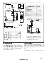
Page 5: ...22 337 440 38 552 57 762 587 103 83 25 552 165 676 135 441 01 2613 05 5 Specifications are subject to change without notice Figure 1 Dimensions and Clearances N8MPN L MINIMUM CLEARANCES TO COMBUSTIBLE MATERIALS FOR ALL UNITS REAR 0 FRONT combustion air openings in furnace and in structure 3 76 mm Required For Service 30 762 mm ALL SIDES Of SUPPLY PLENUM 1 25 mm SIDES 0 VENT Single Wall Vent 6 152 ...

Page 6: ... 1 25 mm TOP OF FURNACE 1 25 mm 30 762 mm clearance recommended for furnace removal Horizontal position Line contact is permissible only between lines formed by intersections of top and two sides of furnace jacket and building joists studs or framing Furnace Capacity Cabinet Top Bottom Return Air Opening A B F C D 8MPL050B12 8MPL075B12 151 2 394 14 356 6 152 13 8 35 125 8 321 H 8MPL075F16 8MPL100F...

Page 7: ...the front of the furnace louver door This is a recommendation only not a requirement This furnace MUST NOT be installed directly on carpeting tile or other combustible material other than wood flooring or supports Downflow FIRE HAZARD Failure to follow this warning could result in personal injury death and or property damage Place furnace on noncombustible subbase on downflow applications unless i...

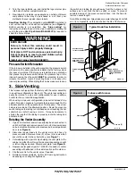
Page 8: ...rnace See side venting for venter rotation Typical Downflow Installation Figure 5 VENT GAS SUPPLY MUST BE OPPOSITE VENT DISCHARGE SIDE SUPPLY AIR RETURN AIR OPTIONAL VENT 25 23 19 Combustible floor base outlet flange adapter Vent Shield Kit 3 Side Venting This furnace is shipped from the factory with the venter assembly in an upflow configurations top vent The venter assembly can easily be rotated...

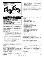
Page 9: ...certain areas or types of structures could cause excessive exposure to contaminated air having chemicals or halogens that will result in safety and performance related problems and may harm the furnace These instances must use only outdoor air for combustion The following areas or types of structures may contain or have exposure to the substances listed below The installation must be evaluated car...

Page 10: ... the enclosure Appliances shall have clearances of at least 1 25 4mm from the sides and back and 6 152 4mm from the front The opening shall directly communicate with the outdoors or shall communicate through a vertical or horizontal duct to the outdoors or spaces crawl or attic that freely communicate with the outdoors 4 Combination of Indoor and Outdoor Air shall have a Indoor openings that compl...

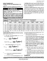
Page 11: ... 210 9 375 262 5 11 250 316 0 10 6 300 176 4 8 400 235 2 10 500 294 7 500 210 11 250 315 15 000 420 18 750 525 22 500 632 0 00 NP NP NP NP NP NP NP NP NP Not Permitted Table 2 Minimum Space Volumes were determined by using the following equations from the National Fuel Gas Code ANSI Z223 1 NFPA 54 2009 9 3 2 2 1 For other than fan assisted appliances such as a draft hood equipped water heater 1000...

Page 12: ...s Code Code ANSI Z223 1 NFPA 54 2009 Sections 12 and 13 venting requirements in the United States or the National Standard of Canada Natural Gas and Propane Installation Code NSCNGPIC CSA B149 1 05 Section 8 and appendix C venting requirements in Canada 4 Push the vent connector onto the furnace flue collar of the venter assembly until it touches the bead at least 5 8 15 9mm overlap and fasten wit...

Page 13: ...ned with either Type B vent sized in accordance with ANSIZ223 1 NFPA 2009 tables 13 1a or 13 1b or a listed metal lining system See Masonry Chimney Venting of these instructions Listed corrugated metallic chimney liner systems in masonry chimneys shall be sized by using ANSIZ223 1 NFPA 2009 section 13 1 7 for dedicated venting and 13 2 20 for common venting with the maximum capacity reduced by 20 ...

Page 14: ...an Direct Vent Termination Clearance Figure 10 A05013 V V 14 441 01 2613 05 Specifications are subject to change without notice National Excelsior Company www excelsiorhvac com Subject to change without notice ...

Page 15: ...nd Solid Fuel Burning Appliances ANSI NFPA 211 2006 in the United States and to a Provincial or Territorial Building Code in Canada in its absence the National Building Code of Canada and must be in good condition U S A Refer to Sections 13 1 9 or 13 2 22 of the ANSI Z223 1 NFPA 54 2009 or the authority having jurisdiction to determine whether relining is required If relining is required use a pro...

Page 16: ...CHIMNEY INSPECTION CHART For additional requirements refer to the National Fuel Gas Code ANSI Z223 1 NFPA 54 2009 and ANSI NFPA 211 2006 Chimneys Fireplaces Vents and Solid Fuel Burning Appliances in the U S A or to the Canadian Installation Code CSA B149 1 05 in Canada Yes No No Mortar or tile debris Yes Remove mortar and tile debris No Remove metal vent or liner Consult Part B of chimney adapter...

Page 17: ...ed Type B vent Relining with a listed metal liner or Type B vent is considered to be a vent in a chase If a metal liner or Type B vent is used to line a chimney no other appliance shall be vented into the annular space between the chimney and the metal liner APPLIANCE APPLICATION REQUIREMENTS Appliance operation has a significant impact on the performance of the venting system If the appliances ar...

Page 18: ...ce with all building codes NOTE In the state of Massachusetts a Gas supply connections MUST be performed by a licensed plumber or gas fitter b When flexible connectors are used the maximum length shall not exceed 36 914 4mm c When lever handle type manual equipment shutoff valves are used they shall be T handle valves d The use of copper tubing for gas piping is NOT approved 1 Install gas piping i...

Page 19: ...e the elbows so that the outlet of one 1 elbow is 90 from the inlet of the other The elbows should be tight enough to be leak proof An additional 1 4 turn will be required at the end of step 2 see Figure 13 Figure 13 25 23 23c Elbows N8MP 2 Screw elbow assembly into gas valve far enough to be leak proof Position elbow assembly so that the inlet of the elbow is at the top of the gas valve An additi...

Page 20: ...sed Propane gas dealer make all connections at storage tank and check all connections from tank to furnace If copper tubing is used it MUST comply with limitation set in local codes or in the absence of local codes the gas codes of the country having jurisdiction Two stage regulation of Propane gas is recommended FIRE OR EXPLOSION HAZARD Failure to follow this warning could result in personal inju...

Page 21: ...on all wires away from sharp edges and moving parts Do not pinch J Box wires or other wires when reinstalling blower compartment door 8MPN L Models The J Box is installed in the burner compartment on left side of casing An alternate J Box location on right side can be used 1 Remove and save two screws holding J Box to casing 2 Move large hole plug from right to left J Box location 3 Clip wire tie ...

Page 22: ...OT draw return air from inside a closet or utility room where furnace is located Return air duct MUST be sealed to furnace casing WARNING Duct Connections This furnace may be installed in only a bottom or side return air duct application Return air duct connections through the back of the furnace is NOT permitted Upflow ONLY Side return air duct connections can be made by cutting out the embossed ...

Page 23: ... filter MUST be used Filters are not supplied with these furnaces but can be purchased from your distributor See Table 4 for required high velocity filter sizes Table 4 High Velocity Air Filter Sizes max 600 FPM 3 0 m s Cabinet Width in mm Internal Filter in mm External Filter Rack Bottom Bottom Side 151 2 393 7 14 X 25 355 6 x 635 14 X 25 355 6 x 635 14 X 25 355 6 x 635 or 16 X 25 508 x 635 191 8...

Page 24: ...ps first and push filter back until it is fully engaged into back clip Center Clip side to side Figure 25 Bottom Mounted Filter 25 24 18 1 9 Figure 26 Filter Clip Construction in mm 26 Ga Galvanized Steel FAST part number 1008482 3 11 4 11 2 11 16 76 2 38 1 31 8 27 NOTE If filters are only suitable for heating application advise homeowner that filter size may need to be increased if air conditioni...

Page 25: ... bent outward and flat to mate the outlet of the furnace to the cased coil Sub Bases for Combustible Floors Furnace Only Note When using the subbase for combustible floors the discharge air duct flanges on the furnace MUST be broken down to provide proper fit up to the subbase Use duct pliers to bend the duct flanges flat onto the furnace casing DO NOT bend the duct flanges inward toward the heat ...

Page 26: ...mm shorter and 11 8 28 6mm narrower than the minimum required size of the opening in the floor This is done to maintain a 1 25 4mm clearance between the floor and the plenum 2 Fabricate the plenum to the dimensions given in Table 5 Note that the dimensions given are outside dimensions 3 Set the base over the opening in the floor centering the opening in the base over the opening in the floor Faste...

Page 27: ...old pressure with burners operating FIRE OR EXPLOSION HAZARD Failure to follow this warning could result in personal injury death and or property damage Turn OFF gas at shut off before connecting manometer WARNING 1 With gas OFF connect manometer to manifold pressure tap on outlet of gas valve See Figure 32 Use a manometer with a 0 to 12 in wc range Typical Gas Valve Regulator Adjustment Under Cap...

Page 28: ...titude gas conversion shall be done by a qualified service agency in accordance with the Manufacturer s instructions and all applicable codes and requirements or in the absence of local codes the applicable national codes WARNING These furnace may be used at full input rating when installed at altitudes up to 2000 When installed above 2000 610m the input must be decreased 2 natural or 4 Propane fo...

Page 29: ...EVEL ft m 0 to 2000 0 to 610 2001 to 3000 610 to 914 3001 to 4000 915 to 1219 4001 to 5000 1220 to 1524 5001 to 6000 1524 to 1829 6001 to 7000 1829 to 2134 7001 to 8000 2134 to 2438 2500 10 0 10 0 9 0 10 0 9 4 8 5 10 0 Orifice Size 54 54 54 55 55 55 56 Conversion 1 in wc 25 kPa NOTE Propane data is based on 1 53 specific gravity For fuels with different specific gravity consult the National Fuel G...

Page 30: ...cessory kit is re quired when operating the furnace with Propane gas WARNING 8MPLs and N8MPLs contain NOx inserts FOR PROPANE CONVERSION REMOVE SCREWS THAT SECURE THE NOX INSERT AND DISCARD INSERT Reinstall screws See Figure 36 NOTE It is very important to reinstall the NOx insert mounting screws Figure 35 Removing NOx inserts 25 40 03 Main Burner Flame Check Allow the furnace to run approximately...

Page 31: ...m the Heat or Cool terminal and replace it with the desired motor speed lead from the M1 or M2 location Connect the wire previously removed from the Heat or Cool terminal to the vacated M1 or M2 terminal 3 If the same speed must be used for both heating and cooling remove the undesired motor speed lead from the Heat or Cool terminal and connect that lead to the open terminal at M1 or M2 location o...

Page 32: ... s Information Manual ELECTRICAL SHOCK FIRE OR EXPLOSION HAZARD Failure to follow this warning could result in dangerous operation personal injury death or property damage Improper servicing could result in dangerous operation injury death or property damage Before servicing disconnect all electrical power to furnace lockout and tag switch with a suitable warning label When servicing controls labe...

Page 33: ...wer demands from furnace control Fan demands from furnace control for heat cool or G will override hard wired speed tap NOTE 3 EAC is NOT active for hard wired mode but IS active for fan demands from furnace control for heat cool and G Heating W Request Heating W Request 24 VAC signal applied to W terminal of FCB Inducer motor turns on and the pressure switch es close s Following a 15 second prepu...

Page 34: ...t Normal operation or no previous Diagnostic Code ON SOLID Soft Lockout Furnace Control Error 1 hr delay If code repeats immediately following power reset then replace control 1 Flash Not used 2 Flashes Pressure switch es closed when should be open 3 Flashes Pressure switch open when should be closed 4 Flashes Limit or roll out switch open less than 2 minutes 5 Flashes Flame sensed out of sequence...

Page 35: ...B2 N8MPL125J22B2 N8MPN125J22B2 8MPN050B12B2 8MPL050B12B2 8MPN075B12B2 8MPL075B12B2 8MPN075F16B2 8MPL075F16B2 8MPN100F14B2 8MPL100F20B2 8MPN100F20B2 8MPL100J20B2 8MPN100J20B2 8MPL125J20B2 8MPN125J20B2 8MPN150J20B2 Denotes Brand International Comfort Products LLC Lewisburg TN 37091 U S A Save This Manual For Future Reference National Excelsior Company www excelsiorhvac com Subject to change without ...

Page 36: ...let Size Inches 4 4 4 4 4 4 4 4 Limits Controls Thermal Sensor oF oC Limit Control 300 149 See Parts List 300 149 See Parts List 300 149 See Parts List 300 149 See Parts List 300 149 See Parts List 300 149 See Parts List 300 149 See Parts List 300 149 See Parts List Std Pressure Sw Part No Press Close in wc Pa Press Open in wc Pa 1013529 0 69 172 0 59 147 Furnace Control Type Furnace Control On de...

Page 37: ...ze Inches 4 4 4 4 4 4 4 Limits Controls Thermal Sensor oF oC Limit Control 300 149 See Parts List 300 149 See Parts Listt 300 149 See Parts List 300 149 See Parts List 300 149 See Parts List 300 149 See Parts List 300 149 See Parts List Std Pressure Sw Part No Press Close in wc Pa Press Open in wc Pa 1013529 0 69 172 0 59 147 Furnace Control Type Furnace Control On delay Timed secs Off delay Integ...

Page 38: ...ts Controls Thermal Sensor oF oC Limit Control Auxiliary Limit oF oC 300 149 See Parts List 130 54 300 149 See Parts List 130 54 300 149 See Parts List 130 54 300 149 See Parts List 130 54 300 149 See Parts List 130 54 300 149 See Parts List 130 54 300 149 See Parts List 130 54 300 149 See Parts List 130 54 Std Pressure Sw Part No Press Close in wc Pa Press Open in wc Pa 1013529 0 69 172 0 59 147 ...

Page 39: ...it Control Auxiliary Limit oF oC 300 149 See Parts List 130 54 300 149 See Parts List 130 54 300 149 See Parts List 130 54 300 149 See Parts List 130 54 300 149 See Parts List 130 54 300 149 See Parts List 130 54 Std Pressure Sw Part No Press Close in wc Pa Press Open in wc Pa 1013529 0 69 172 0 59 147 Furnace Control Type Furnace Control On delay Timed secs Off delay Integrated 30 60 100 140 180 ...

Page 40: ...s above maximum temperature rise range NOTE 1 Gray area is above maximum temperature rise range CFM Cubic feet per minute airflow L s Liters per second Filter required for each return air inlet Airflow performance includes 1 25 4mm washable 600 FPM 3 0 m s max filter media N8MPN100F14 8MPN100F14 1 8 Denotes Brand Exterrnal Static Pressure in wc Pa Air Delivery in CFM L s Furnace Rated 0 5 in wc 12...

Page 41: ...s 1 25 4mm washable 600 FPM 3 0 m s max filter media N8MPN L125J20 8MPN L125J20 2 5 8 Denotes Brand Exterrnal Static Pressure in wc Pa Air Delivery in CFM L s Furnace Rated 0 5 in wc 125 Pa ESP TAP LOW MED L MED H HIGH in wc Pa CFM L s CFM L s CFM L s CFM L s 0 1 25 860 406 1149 542 1666 786 2147 1013 0 2 50 848 400 1154 545 1622 765 2137 1008 0 3 75 836 395 1158 546 1577 744 2126 1003 0 4 100 821...

Page 42: ...441 01 2613 05 42 Specifications are subject to change without notice Wiring Diagram N8MPN L 8MPN L National Excelsior Company www excelsiorhvac com Subject to change without notice ...

Page 43: ...fied installer service agency local gas supplier or your distributor or branch for information or assistance The qualified installer or agency must use only factory authorized and listed kits or accessories when modifying this product WARNING PRODUCT NOMENCLATURE 8 MP L 0 75 B 1 2 B Brand Specific Engineering Rev Brand Efficiency Denotes minor change 8 Non Condensing 80 Gas Furnace 9 Condensing 90...

Page 44: ...44 Specifications are subject to change without notice 441 01 2314 05 THIS PAGE LEFT BLANK INTENTIONALLY National Excelsior Company www excelsiorhvac com Subject to change without notice ...

Reviews: