

Printed in U.S.A.
440 04 4321 02
Aug. 2011
SERVICE AND TECHNICAL
SUPPORT MANUAL
TwoStage, ECM Blower Motor
35” Tall, High Efficiency Condensing Gas Furnace
(F/G)9MXT
Save this manual for future reference.
Safety Labeling and Signal Words
DANGER, WARNING, CAUTION, and NOTE
The signal words
DANGER, WARNING
,
CAUTION
,
and
NOTE
are used to identify levels of
hazard seriousness. The signal word
DANGER
is
only used on product labels to signify an immediate
hazard. The signal words
WARNING
,
CAUTION
,
and
NOTE
will be used on product labels and
throughout this manual and other manual that may
apply to the product.
DANGER
Immediate hazards which will result in
severe personal injury or death.
WARNING
Hazards or unsafe practices which
could result in severe personal injury or death.
CAUTION
Hazards or unsafe practices which
may result in minor personal injury or product or
property damage.
NOTE
Used to highlight suggestions which will
result in enhanced installation, reliability, or
operation.
!
WARNING
Signal Words in Manuals
The signal word
CAUTION
is used throughout
this manual in the following manner:
!
CAUTION
Signal Words on Product Labeling
Signal words are used in combination with
colors and/or pictures or product labels.
The signal word
WARNING
is used throughout
this manual in the following manner:
Safetyalert symbol
When you see this symbol on the unit and in
instructions or manuals, be alert to the
potential for personal injury.
TABLE OF CONTENTS
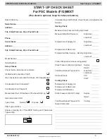
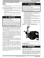
STARTUP, ADJUSTMENT, AND SAFETY CHECK
4
. . . . . . . . . . .
THERMOSTAT SETUP SWITCH
4
. . . . . . . . . . . . . . . . . . . . . . . . . . .
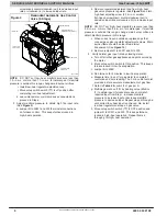
PRIME CONDENSATE TRAP WITH WATER
4
. . . . . . . . . . . . . . . . .
PURGE GAS LINES
4
. . . . . . . . . . . . . . . . . . . . . . . . . . . . . . . . . . . . . .
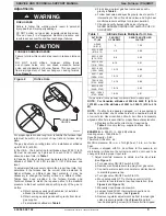
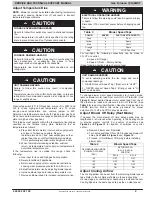
ADJUSTMENTS
5
. . . . . . . . . . . . . . . . . . . . . . . . . . . . . . . . . . . . . . . . .
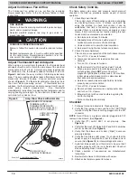
ADJUST TEMPERATURE RISE
9
. . . . . . . . . . . . . . . . . . . . . . . . . . . .
ADJUST BLOWER OFF DELAY (HEAT MODE)
9
. . . . . . . . . . . . . .
ADJUST COOLING AIRFLOW
9
. . . . . . . . . . . . . . . . . . . . . . . . . . . . .
ADJUST CONTINUOUS FAN AIRFLOW
10
. . . . . . . . . . . . . . . . . . . .
ADJUST THERMOSTAT HEAT ANTICIPATOR
10
. . . . . . . . . . . . . . .
CHECK SAFETY CONTROLS
10
. . . . . . . . . . . . . . . . . . . . . . . . . . . . .
CHECKLIST
10
. . . . . . . . . . . . . . . . . . . . . . . . . . . . . . . . . . . . . . . . . . . . .
SERVICE AND MAINTENANCE PROCEDURES
12
. . . . . . . . . . . . .
ELECTRICAL CONTROLS AND WIRING
12
. . . . . . . . . . . . . . . . . . .
TROUBLESHOOTING
12
. . . . . . . . . . . . . . . . . . . . . . . . . . . . . . . . . . . .
CLEANING AND/OR REPLACING AIR FILTER
14
. . . . . . . . . . . . . .
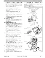
BLOWER MOTOR AND WHEEL MAINTENANCE
14
. . . . . . . . . . . .
CLEANING BURNERS AND FLAME SENSOR
16
. . . . . . . . . . . . . . .
SERVICING HOT SURFACE IGNITER
17
. . . . . . . . . . . . . . . . . . . . . .
FLUSHING COLLECTOR BOX AND DRAINAGE SYSTEM
17
. . . .
CLEANING CONDENSATE DRAIN AND TRAP
18
. . . . . . . . . . . . . .
CLEANING HEAT EXCHANGERS
18
. . . . . . . . . . . . . . . . . . . . . . . . . .
SERVICE LABEL
20
. . . . . . . . . . . . . . . . . . . . . . . . . . . . . . . . . . . . . . . . .
WIRING DIAGRAM
21
. . . . . . . . . . . . . . . . . . . . . . . . . . . . . . . . . . . . . . .
SEQUENCE OF OPERATION
24
. . . . . . . . . . . . . . . . . . . . . . . . . . . . .
PARTS REPLACEMENT INFORMATION GUIDE
28
. . . . . . . . . . . . .
PRODUCT NOMENCLATURE
29
. . . . . . . . . . . . . . . . . . . . . . . . . . . . .
MODELS
(F/G)9MXT0401410A
(F/G)9MXT0601714A
(F/G)9MXT0801716A
(F/G)9MXT1002116A
(F/G)9MXT1202422A
Use of the AHRI Certified TM Mark indicates a
manufacturer’s participation in the program.
For verification of certification for individual
products, go to www.ahridirectory.org .


