background image


R05 


ET xtreme

®


STANDARD TAPE HEAD 

Serial Numbers UH230T, UH430T 

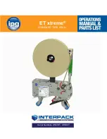
Summary of Contents for ET xtreme Series

Page 1: ...1 R05 ET xtreme STANDARD TAPE HEAD Serial Numbers UH230T UH430T ...

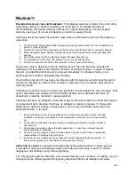
Page 2: ...2 R05 ...

Page 3: ...ing AdaptersUUUTTTHHH 15 HHHTUTUTUTape LoadingUUUTTTHHH 16 HHHTUTUT UTape ThreadingUUUTTTHHH 17 Tape Centering 19 HHHTUTUT UTape Leg Length AdjustmentUUUTTTHHH 21 HHHTUTUTU One Way Clutched Roller AdjustmentUUUTTTHHH 22 HHHTUTUTU Main Spring AdjustmentUUUTTTHHH 22 HHHSection 8 HHHTUTUTUTroubleshootingUUUTTTHHH 25 Section 9 HHHTUTUTURecommended Spare Parts ListUUUTTTHHH 28 Section 10 HHHTUTUTUPreve...

Page 4: ...ffixed to the Cover Frame of the Tape Head Interpack Technical Support is available during normal business hours 8 30 a m to 5 00 p m Eastern Time Tel 1 800 474 8273 Option 3 If you have a technical question that does not require an immediate response you may contact Interpack by fax Fax 1 800 462 1293 Technical support may also be contacted via email at the address below Email machsupp itape com ...

Page 5: ...ve 5 calendar days after the warranty period If Intertape is unable to repair or replace the part within a reasonable time then Intertape at its option will replace the equipment or refund the purchase price Intertape shall have no obligation to install the repaired or replacement part Intertape shall have no obligation to provide or pay for the labor required to install the repaired or replacemen...

Page 6: ...sensitive carton sealing tape to the top and bottom center seam of regular slotted corrugated cartons The ET xtreme can be configured into all Interpack case sealers This ET xtreme is also designed to upgrade most competitive case sealers Interpack can provide a variety of adaptor kits to install this tape head into most case sealers ...

Page 7: ...rvice information Only trained personnel are to operate and service Tape Head Wear safety glasses Shut off power to machine before adjusting Unplug electrical power before servicing All covers and guards must be in place before operating Stay clear of moving parts which can shear and cut Never operate the Tape Heads with the Knife Guard removed Turn electrical supply off before servicing the Tape ...

Page 8: ...the guard itself are being replaced Should the tape head be operated without blade guard user voids all warranty implied the manufacturer bears no responsibility for the consequences Tape head shall never be serviced while mounted in a machine Figure 5 1 Label on Figure 5 2 is visible on carton sealing machine Figure 5 2 While the tape head is processing cartons or it is in motion keep your hands ...

Page 9: ... each tape head The label provides operators and service personnel the proper method of threading a new roll of tape through the tape head More detailed information is provided in the Set Up Procedures portion of this manual Turn air and electrical supplies off before servicing the tape heads Figure 5 4 ...

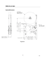
Page 10: ...10 R05 SPECIFICATIONS UUUTape Head Dimensions Figure 6 1 ...

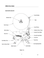
Page 11: ...11 R05 SPECIFICATIONS UUU Tape Head Components Figure 6 2 ...

Page 12: ...2mm 3 Tape Roll Diameter Maximum of 16 inches 405 mm on a 3 inch 76 86 mm diameter core Accommodates all Intertape brand film tape machine roll lengths 4 Tape Application Leg Length Standard 2 70 3mm 5 Tape Application Leg Length Optional The tape leg length can be adjusted from 2 inches to 3 inches 50 mm to 76 mm 6 Tape Head Weight ET xtreme 2 Tape Head weighs 9 lbs 4 kg ET xtreme 3 Tape Head wei...

Page 13: ...del and serial number on hand 1 The case must be positively propelled through the case sealer taking into account any void fills overfills stability factors or weight factors 2 Verify the case sizes which will be processed through the case sealer Installing Interpack ET xtreme tape heads to process very short cases may cause the tape heads to collide with each other 3 If a flight bar or lug drive ...

Page 14: ...ounting adaptors part no ADA15 4 Mounting adaptors part no ADA10 4 4 Mounting adaptors part no ADA03 4 SS Main spring part no UPH1091 1 1 SS Ext Main spring part no UPH0910 1 1 Knife arm spring part no UPH7427 1 1 Operational manual parts list 1 1 Note After unpacking the Tape Head look for any damage that may have occurred during shipping Should the Tape Head be damaged file a claim with the tran...

Page 15: ...ase sealer or case erector you do not need to follow any instructions from this section If your tape heads will be installed in any other brand machinery please review these general guidelines plus any additional instructions included with your ET xtreme tape head Location Of Mounting Adapter Holes Cover Plate Side Figure 7 1 Main Plate Side Figure 7 2 Examples Of Mounting Hardware There are four ...

Page 16: ...riction washer temporarily 3 Push the roll of tape onto the mandrel with the adhesive side facing away from the peel Off Roller refer to Threading Diagram on Figure 5 4 under Tape Threading section in this manual until the core sits against the mandrel flange The hooked red sprag should latch onto the tape core While removing the tape this should be pressed down to free the tape 4 Loosen friction ...

Page 17: ...AVOID PERSONNEL INJURY Tape Threading Preparation Threading the tape in the Tape Head does not require any special tools Pull approximately twelve 12 inches of tape from the roll and fold in half lengthwise adhesive side to adhesive side This allows you to thread the tape without it adhering to the guide and clutch rollers inside the Tape Head 12 Figure 7 5 ...

Page 18: ...the smooth Guide Roller 4 Continue threading the tape over and behind the final knurled Guide Rollers 5 Thread the tape through the cut out provided in the Tape Guide Shoe and pull the tape through to the front of the Application Roller ensuring that the tape is retained in the tape guide shoe 6 Cut off the folded tape 7 Replace the Tape Head to its initial position in the machine Adhesive Side Gu...

Page 19: ...n the M18 inverse jam nut on the rear of the mandrel as shown in Figure 7 8 with a 10 mm allen key Turn it counterclockwise to unlock it Adjust the shaft in or out as required using a flathead screwdriver as illustrated in Figure 7 9 When the tape is centered tighten the jam nut Note One full turn will result in 1mm tape deplacement Figure 7 9 Figure 7 8 10mm HEX KEY JAM NUT ...

Page 20: ...6mm 1 tape on a 2 mandrel hub and the 60mm 2 tape on a 3 mandrel hub 1 Position the Spacer Ring in front of the mandrel hub in a way that the notches of the Spacer Ring will align with the Sprags on the mandrel hub as shown in Figure 7 10 2 Push the Spacer Ring all the way on the mandrel hub as shown in Figure 7 11 3 It will take a second Spacer Ring to sandwich the tape roll into position Figure ...

Page 21: ... tape leg Re tighten both M6 Flat Head Cap Screws To adjust the tape leg length on the trailing end of the box both knife arm extension brackets must be re positioned in unison Unscrew the three 3 M4 Screws on each knife arm extension using a 2 5 mm hexagonal key For a UUUShorter Tape LegUUU bring the knife arm towards the UUUfrontUUU of the tape head Conversely for a UUULonger Tape LegUUU bring t...

Page 22: ... sealing results before going any further Once the disc spring has been over squeezed it may lose its properties To avoid this eventuality pay attention The main spring retainers are set at the factory for the most common applications The top tape head will need lighter springs UPH0910 or UPH0911 while the bottom positioned tape head will need heavier springs UPH1091 The ET X 3 inch tape heads can...

Page 23: ... and move a position up farther away from the pivot axis 2 1 3 The previously listed 3 options may need to be employed in combination to get the best result For instance to get the 3 inch tape head in top tape head mode at 120 ft min line speed make the following set up refer to Figure 8 3 Put the M6 FHCS item 1 on rear arm on the second position from pivot shaft Put the M6 FHCS Item 3 on the Cove...

Page 24: ...10mm open end wrench turn the 6mm nylon lock nut clockwise until desired pressure achieved 2 To decrease the force using a 10mm open end wrench turn the nylon lock nut counterclockwise so that the pressure on top flaps is reduced but it still cuts the tape Figure 8 4 M6 NUT 10mm WRENCH ...

Page 25: ...ntenance section for details Replace Knife Arm Spring Refer to preventive maintenance section for details Slightly increase the tension on the one way clutched roller Front tape leg too short Generally too much tension on the application of the tape Tape threaded incorrectly Tape leg length misadjusted Follow corrective action in Tape Flagging section below Check for proper tape threading against ...

Page 26: ...ld spin freely Check for any adhesive migration or build up Mandrel does not spin freely even after tension is reduced Too much one way clutch roller tension Tape unwind is difficult Cutter blade is dull Remove any adhesive build up with silicon spray Disassemble any non free spinning rollers and remove any adhesive build up on shafts Disassemble mandrel assembly and check debris Decrease clutch r...

Page 27: ...pe Flagging section above Adjust knife arm extensions Rear tape leg too long Tape threaded incorrectly Tape leg length misadjusted Check for proper tape threading against threading diagram on side plate of tape head Ajust knife arm extensions Tape not centered on the center seam of the case Check the box are the flaps overlapping on each other Check if the whole tape head is mounted in between the...

Page 28: ...eferenced should individual components need to be ordered ET xtreme Standard 2 Wide Spare Parts Kit UH1010 Parts Contained in UH 1010 Spare Parts Kit MODEL NUMBER DESCRIPTION ITEM NUMBER QUANTITY Front Roller 2 UPH1448 1 Independent Wiper Tabs 2 UPH4894 1 Ext spring light UPH0999 1 Ext spring light SS UPH0910 1 Knife guard spring UPH7009 1 Cut off blade 2 SS NC UPH0193 1 SS Main Spring ETM 080 UPH...

Page 29: ...Contained in UH 1011 Spare Parts Kit MODEL NUMBER DESCRIPTION ITEM NUMBER QUANTITY Front Roller 3 UPH1449 1 Independent Wiper Tabs 3 UPH4895 1 Ext spring light UPH0999 1 Ext spring light SS UPH0910 1 Knife guard spring UPH7009 1 Cut off blade 3 SS NC UPH0271 1 SS Main Spring ETM 080 UPH1091 1 ...

Page 30: ...e performance and prolong the life of the tape head Please review the illustration and chart below for information regarding tape head maintenance UUUKnife Blade Replacement The knife blade is made from stainless steel and should provide a minimum of 250 000 cycles before replacement The cut off blade is secured in position using two 2 M5 Button Head Cap Screws To replace the cut off blade 1 Loose...

Page 31: ...nt of lightweight oil mineral oil food grade 70 or silicon spray so that when a case is processed the oil from the pad is transferred to the blade as the knife guard is opened and closed refer to Preventative Maintenance on pg 40 for further information UUUOiler Pad Lubrication WARNING USE CAUTION WHEN OILING THIS PAD AS THE CUTTER BLADE IS VERY SHARP DO NOT OPERATE THE TAPE HEAD WITHOUT THE FELT ...

Page 32: ...applying soapy water or foam 2 Feed the urethane roller onto the end of the roller core The closed air pocket will help the urethane tube to hop over the core 3 Press the urethane roller until it reaches the roller core s rim shoulder do not exert excessive force so that the rim would crack 4 Place roller back onto the shaft rimmed side closer to main frame 5 To reinstall back into the roller arm ...

Page 33: ... most common springs Main Spring Replacement 1 Using a spring puller tool remove one end of the main spring from the spring retainer 2 Take off the damaged spring 3 Hook one end of the new spring over the nylon spring retainer sleeve s groove 4 Stretch the spring over rear arms spring retainer ring using either a spring puller 10 approx or your fingers Hook the loop securely into the retainer s gr...

Page 34: ... assembly Wear safety glasses while working with retaining rings Figure 10 6 2 Slide off the repulsive pivot assembly from current position as shown in Figure 10 7 Figure 10 7 3 Remove the spring barrel from over lapping position as shown in Figure 10 8 Remove any broken particle from the spring guide Install new compression spring into the captive position Figure 10 8 Snap Ring ...

Page 35: ... short shaft See Figure 10 9 Move the whole sub assembly back to its original position 5 Reinsert retaining ring to the groove Should the 10 mm retaining ring get damaged replace it with a new one Figure 10 10 Calibrate the spring pressure with the M6 nylon lock nut as described earlier Snap Ring Figure 10 9 Figure 10 10 ...

Page 36: ... removal 1 Using two 2mm hexagonal keys as shown remove one of the flathead screws by applying force on both hexagonal key in an attempt to break free one from locking agent 2 Once one of the screws is free only continue to remove that screw 3 Leave the remaining flathead screw that did not yield attached to the cross shaft Figure 10 12 2mm Hex Key As a precaution remove the cutter blade to avoid ...

Page 37: ...37 R05 PREVENTIVE MAINTENANCE Carefully slide out the shaft from the end of the shaft that contains the remaining flathead screw Remove the broken spring Figure 10 13 Figure 10 14 ...

Page 38: ... Figure 10 15 2 Note which leg of the spring should lie behind the cutter blade mounting plate 3 Note that the looped leg shall wrap around the blade guard Insert the cross shaft through the knife arm knife guard and knife guard spring as shown in Figure 10 16 Behind The Cutter Blade Mounting In Front Of Knife Guard Figure 10 15 ...

Page 39: ...shown in Figure 10 17 2 The shaft should not vacillate in the mounting holes 3 Rotate the knife guard to make sure there is no binding 4 Re install the cutter blade as shown in Figure 10 11 5 Inspect the oiler pad to make sure it is securely fastened Clean the pad and apply some lightweight oil 6 Check that the magnet catch is spinning free if not spray the pin with silicon based lubricant Figure ...

Page 40: ... adhesive into the corrugated fiber Over time this tab can become distorted or worn and should be replaced Dual Wiper Tabs Replacement 1 Remove the two M4 hex nuts Item 1 from the rear arm with a 7mm wrench 2 Unscrew the two M4 bottom head countersink screws item 2 3 Remove the rectangular washer Item 3 and the dual Wiper Tabs Item 4 4 Install new Wiper Tabs with two M4 button head screws as shown...

Page 41: ...E Guide Rollers Rotation should be slightly restricted by spring Disassemble and remove any adhesive build up if excessive restriction is detected Check one way bearing grease bearing Oiled string and Damp Cloth X Front Blue Wipe Down Roller Rotation should be slightly restricted by spring washer Disassemble and remove any adhesive build up if excessive restriction is detected Solvent Cleaner X Re...

Page 42: ...rm Assembly 50 Guide Roller 52 Tape Shoe Assembly 54 Front Roller 56 Rear Arm Assembly 58 Link Assembly 60 Knife Arm Assembly 62 Clutch Assembly 64 Clutch Roller 66 Mandrel Assembly 68 Mandrel Arm Sub Assembly 70 Mandrel Hub 72 Repulsive Pivot Assembly 74 Peel Off Assembly 76 No Tape Sensor Option 78 Low Tape Sensor Option 80 ...

Page 43: ...43 R05 THIS PAGE INTENTIONALLY LEFT BLANK ...

Page 44: ...4 6 10 8 1 9 3 5 7 2 11 12 13 44 ...

Page 45: ...SEMBLY 1 4 USH1103 REAR ARM ASSEMBLY 1 5 USH4133 LINK ASS Y 1 1 6 USH1122 KNIFE ARM ASS Y 2 1 6 USH1123 KNIFE ARM ASS Y 3 1 7 USH1124 CLUTCH ASSEMBLY 1 7 USH1125 CLUTCH ASSEMBLY 1 8 USH1126 MANDREL ASSEMBLY 1 8 USH1127 MANDREL ASSEMBLY 1 9 USH1129 REPULSIVE PIVOT ASS Y SS 1 1 10 USH1111 PEEL OFF ASSEMBLY 2 1 10 USH1112 PEEL OFF ASSEMBLY 3 1 11 UPH1424 SAFETY COVER 2 1 11 UPH1314 SAFETY COVER 3 1 1...

Page 46: ...1 15 2 3 6 10 12 14 7 11 8 9 5 4 16 14 13 13 4 18 17 46 ...

Page 47: ...m Dia W SNAP RING 1 6 UF3282 SS FHCS M5 0 8 x 12 mm 1 1 7 UF3277 SS FHCS M5 0 8 x 16 mm 8 8 8 UPH3856 SS FLAT WASHER 1 1 9 UPH4886 SPACER WASHER 1 1 10 UPH133 URETHANE STOP 2 2 11 UPH1417 URETHANE STOP 1 1 12 UPH1017 SS STOP RETAINER 3 3 13 UF6336 F W PTFE 13 x 19 x 1 mm 2 2 14 UF6335 F W PTFE 12 5 x 20 x 0 55 mm 2 2 15 UF7012 SS FHCS M5 0 8 x 8 mm 2 2 16 UF7017 SS RET G RING EXTERNAL 12mm 1 1 17 ...

Page 48: ...6 11 8 14 2 12 9 7 10 5 3 3 13 48 ...

Page 49: ...UF7012 SS FHCS M5 0 8 x 8 mm 2 2 5 UPH4041 SPACER BAR 1 5 UPH1368 SPACER BAR 1 6 UPH1365 COVER FRAME 1 1 7 UPH1417 URETHANE STOP 1 1 8 UPH133 URETHANE STOP 1 1 9 UPH1017 SS STOP RETAINER 2 2 10 UF3282 SS FHCS M5 0 8 x 12 mm 1 1 11 UPH4886 SPACER WASHER 1 1 12 UF3556 RETAINING RING 9 mm SS 1 1 13 UF9170 SS FHCS M3 0 5 x 12 2 2 14 UPH3908 RETAINER MAIN SPRING 1 49 ...

Page 50: ...6 7 15 11 10 14 4 2 9 3 5 13 12 8 1 16 50 ...

Page 51: ...H0209 TAPE SHOE ASS Y 3 1 7 UPH1442 SHAFT 10mm Dia 1 7 UPH1441 SHAFT 10mm Dia 1 8 UF3277 SS FHCS M5 0 8 x 16 mm 2 2 9 UAH0222 FRONT ROLLER ASS Y 48 1 9 UAH0223 FRONT ROLLER ASS Y 72 1 10 UF3261 SS FHCS M6 1 x 16 mm 2 2 11 UPH1446 SHAFT 8 mm Dia 1 11 UPH1447 SHAFT 8 mm Dia 1 12 UF3761 SS FHCS M4 0 7 x 12mm 2 2 13 UF9170 SS FHCS M3 0 5 x 12 2 2 14 UF4511 SS RET RING EXT 8mm 1 1 15 UF5608 SPECIAL WAS...

Page 52: ... 8 8 ...

Page 53: ... 7 0 3 57 6 5 37 21 8 47 8 47 83 8 52 5 83 2035 66 21 635 1 83 8 52 5 ...

Page 54: ...2 4 1 5 3 54 ...

Page 55: ...DESCRIPTION UAH0208 2 QTY UAH0209 3 QTY 1 UPH1434 TAPE SHOE 2 1 2 UPH1435 TAPE SHOE 3 1 2 UPH1438 STIFFENER BLOCK 1 1 3 UF6350 SS FHCS M3 0 5 x 8 mm 1 1 4 UPH7010 SS COMPRESSION SPRING 1 1 5 UPH1510 FINGER 1 1 55 ...

Page 56: ... 8 8 ...

Page 57: ... 7 0 3 57 6 5 37 21 8 47 8 47 83 52 5 25 83 52 5 25 83 66 2035 66 21 635 1 8 37 PP 83 5217 52 5 83 5217 52 5 8 6 635 1 LG RG 8 37 PP 83 6 7 PP 83 6 7 PP ...

Page 58: ... 86 86 ...

Page 59: ... 1 635 1 5 7 1 5 6 9 83 5 7 1 5 83 5 7 1 5 8 66 6 0 8 66 6 0 PP 83 3 927 1 5 1 PP 83 5 5 3 52 5 83 5 5 3 52 5 83 6 7 5 5 50 83 6 7 5 5 50 8 66 5 7 5 1 7 PP 83 8 1 3 1 17 3 5 7 6 83 8 1 3 1 17 3 5 7 6 8 66 187 0 8 66 6 0 PP 8 5 7 1 1 5 1 PP 66 83 5 7 1 8 5 6 5 83 5 7 1 8 5 6 5 8 66 666 0 ...

Page 60: ...2 4 1 3 5 6 5 60 ...

Page 61: ...ITEM PART DESCRIPTION QTY 1 UPH4802 LINK ROD 1 2 UPH4803 ROD END BEARING 8mm 2 3 UPH4801 ROD EYE SUPPORT 1 4 UF3735 SS HNR M8 1 25 2 5 UF5608 SPECIAL WASHER 2 6 UF6337 F W PTFE 12 5 x 20 x 0 29 mm 1 61 ...

Page 62: ...2 3 6 5 1 8 4 12 9 7 9 10 11 62 ...

Page 63: ...RD 1 3 UPH9178 SHAFT BLADE GUARD 1 4 UPH4930 KNIFE AEM EXTENSION LEFT 1 1 5 UPH4931 KNIFE ARM EXTENSION RIGHT 1 1 6 UPH0193 SS CUT OFF BLADE 48 1 6 UPH0271 SS CUT OFF BLADE 75 1 7 UF3276 SS BHCS M5 0 8 x 6 2 2 8 UF3557 SS RETAINING RING FOR 10 mm SHAFT 1 1 9 UF6350 SS FHCS M3 0 5 x 8 mm 2 2 10 UF6337 F W PTFE 12 5 x 20 x 0 29 mm 2 2 11 UPH7009 TORSION SPRING 1 1 12 UF7008 SS BHCS M4 0 7 x 6 6 6 63...

Page 64: ...5 15 7 6 12 2 14 4 3 13 10 8 9 1 11 16 64 ...

Page 65: ...TCH SHAFT 1 5 UPH7078 CLUTCH SHAFT 1 6 UF3261 SS FHCS M6 1 x 16 mm 1 1 7 UF3275 SS FHCS M6 1 x 25mm 1 1 8 UF3404 M6 1 0 LOCK U NUT 1 1 9 UF3401 NYLON WASHER 15 3 x 6 5 x 0 55 2 2 10 UF3557 SS RETAINING RING FOR 10 mm SHAFT 1 1 11 UPH8230 DISC SPRING 1 1 12 UF5399 FHCS M5 0 8 x 25 1 1 13 UF6388 NYLON F W 10 5 x 16 x 0 85 1 1 14 UF6389 NYLON WASHER METRIC 1 1 15 UF6402 F W PTFE 12 5 x 17 5 x 0 5 mm ...

Page 66: ...3 1 2 2 1 3 Standard Tape Head Mirror Tape Head 66 ...

Page 67: ...PTION UAH0212 2 QTY UAH0213 3 QTY UAH0226 2 mir QTY UAH0227 3 mir QTY 1 UPH8139 CLUTCH ROLLER 1 1 1 UPH8140 CLUTCH ROLLER 1 1 2 UPH1034 BEARING 12 x 14 x 12 LG SS 1 1 1 1 3 UPH4857 ONE WAY BEARING STAINLESS 1 1 1 1 67 ...

Page 68: ...5 2 10 4 11 3 8 6 7 1 9 12 68 ...

Page 69: ...3 UPH7004 SS HEX SOCKET PLUG 1 1 1 1 4 UPH7687 SHAFT MANDREL 1 1 4 UPH7688 SHAFT MANDREL 1 1 5 UPH1006 SS MANDREL FRICTION WASHER 1 1 1 1 6 UPH7689 NYLON SPACER 1 1 1 1 7 UPH4800 ADJUSTMENT SLEEVE 1 1 1 1 8 UF5904 SS FHCS M5 0 8 x 20mm 1 1 1 1 9 UF3282 SS FHCS M5 0 8 x 12 mm 2 2 2 2 10 UF4512 SS M8 1 0 NYLON LOCK NUT 1 1 1 1 11 UF6335 F W PTFE 12 5 x 20 x 0 55 mm 1 1 1 1 12 UF7028 NYLON WASHER 1 1...

Page 70: ...1 3 2 70 ...

Page 71: ...ITEM PART DESCRIPTION UAH0224 QTY UAH0225 Mir QTY 1 UPH1459 MANDREL HUB 1 1 2 UPH4808 MANDREL ARM 1 2 UPH8150 MANDREL ARM MIRROR 1 3 UF5904 SS FHCS M5 0 8 x 20mm 3 3 71 ...

Page 72: ... 8 8 ...

Page 73: ... 7 0 3 57 6 5 37 21 8 47 8 47 83 0 1 5 83 0 1 5 83 5 1 83 5 1 83 635 22 83 635 22 83 635 83 635 83 2035 66 21 635 1 8 66 0 6 7 33 1 ...

Page 74: ...6 1 2 5 3 4 74 ...

Page 75: ... V2 SS 1 2 UPH7678 SPRING GUIDE V2 1 3 UPH8111 SPRING BARREL V2 3 UPH8123 SPRING BARREL V2 1 4 UPH4665 COMP SPRING 13 7 O D 1 7 W D 50 8 LONG 4 UPH7427 COMP SPRING 13 7 O D 1 7 W D 50 8 L SS 1 5 UF6391 F W 6 x 16 x 1 mm 5 UF6390 SS F W 6 x 16 x 1 1 6 UF3391 SS NYLON LOCK NUT M6 1 0 1 75 ...

Page 76: ...19 4 9 16 6 7 5 8 1 11 3 10 14 12 15 13 18 17 2 20 76 ...

Page 77: ... 1 1 1 1 9 UF3277 SS FHCS M5 0 8 x 16 mm 1 1 1 1 10 UF3283 SS BHCS M5 0 8 X 10mm 2 2 2 2 11 UF3781 SS FHCS M6 1 x 30mm 1 1 1 1 12 UPH1354 PEEL ROLLER 1 1 12 UPH1355 PEEL ROLLER 1 1 13 UPH1351 PEEL OFF ROLLER SHAFT 1 1 13 UPH1353 PEEL OFF ROLLER SHAFT 1 1 14 UF7018 SS RETAINING RING 16 mm SHAFT 1 1 1 1 15 UPH1379 SPACER RING 1 1 1 1 16 UPH1361 SS TORSION SPRING LEFT SQ 1 1 16 UPH1511 SS TORSION SPR...

Page 78: ...1 2 No Tape options are available 78 ...

Page 79: ...ITEM PART DESCRIPTION QTY 1 UPM7328 PHOTOELECTRIC SENSOR PNP 1 2 UPM7329 PHOTOELECTRIC SENSOR NPN 1 79 ...

Page 80: ...1 2 3 Low Tape options are available 80 ...

Page 81: ...ITEM PART DESCRIPTION QTY 1 UPH8169 PHOTOELECTRIC SENSOR PNP 1 2 UPH8144 PHOTOELECTRIC SENSOR NPN 1 3 UF4518 SS BHCS M3 0 5 X 6 2 81 ...

Reviews: