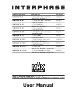
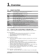
background image

CHART PLOTTER NAME

DESCRIPTION

SOFTWARE

CHART MASTER V6

5.7" Sunlight Readable Color Display

S3egIN7vc

External Smart GPS Receiver

CHART MASTER V6i

5.7" Sunlight Readable Color Display

S3igIN7vc

Internal GPS Receiver

CHART MASTER 7MX

5.6" Gray Levels Display

S3egIN7m

External Smart GPS Receiver

CHART MASTER 7MI

5.6" Gray Levels Display

S3igIN7m

Internal GPS Receiver

CHART MASTER 7CXS

5.6" Sunlight Readable Color Display

S3egIN7c

External GPS Receiver

CHART MASTER 7CI

5.6" Color Display

S3igIN7c

Internal GPS Receiver

CHART MASTER 169CS

7" Sunlight Readable Color Display

S3egIN7wc

External Smart GPS Receiver

CHART MASTER 169CSI

7" Sunlight Readable Color Display

S3igIN7wc

Internal GPS Receiver

CHART MASTER 11 CV+

11" Color Display

S3egIN11c

External Smart GPS Receiver & Video Input

CHART MASTER 11 CVS+

11" Sunlight Readable Color Display

S3egIN11c

External Smart GPS Receiver & Video Input

Copyright 2006 Interphase Technologies Inc. - 

(C1100-250706E)

All rights reserved. No part of this publication may be reproduced or distributed in any form or by any means, or stored in

a database or retrieval system, without prior written permission of the publisher.
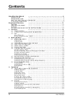
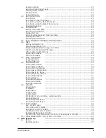
User Manual

Summary of Contents for Chart Master 169CSI

Page 1: ...isplay S3igIN7c Internal GPS Receiver CHART MASTER 169CS 7 Sunlight Readable Color Display S3egIN7wc External Smart GPS Receiver CHART MASTER 169CSI 7 Sunlight Readable Color Display S3igIN7wc Interna...

Page 2: ...Mode 18 Moving around the Chart and Changing Chart Scale 19 Finding Your Boat Position 19 Selecting Look Ahead 19 Selecting Map Orientation 19 2 7 NAVIGATION TO A SINGLE DESTINATION 19 2 8 RANGE BEARI...

Page 3: ...nfo on Lakes 27 Full Info on Lakes 28 3 7 PORT TIDE INFO 28 Getting Port Info 28 Getting Tide Info 29 3 8 FIND FUNCTION 30 Finding Port Service 30 Finding Port By Name 30 Finding Port By Distance 30 F...

Page 4: ...11CVS GPS Cable Wiring page 45 CM 11CV 11CVS AUX IN I O Cable Wiring page 45 Send Receive Routes Marks 45 C Link menu 45 CM 11CV 11CVS External Output 45 4 8 AIS 46 4 8 1 AIS System Definitions 46 4...

Page 5: ...TALLATION AND REMOVING 71 EXTERNAL WIRING 71 TYPICAL CONNECTIONS 72 Autopilot Connection 72 External NMEA Connection 72 GPS Connection For chart plotter with External Smart GPS Receiver 72 C COM GSM P...

Page 6: ...NNECTIONS 84 GPS Connection 84 Autopilot Connection 84 External NMEA Connection 85 External Alarm Connection 85 C COM GSM PLUS Connection 85 CM V6 169CS 7MX 7CXS 11CV 11CVS Installing the Smart GPS Ex...

Page 7: ...P ENTER means press the MENU key using the cursor key select the SETUP menu press the ENTER key select the Map menu and then press ENTER Any menu operation and function activation in this User Manual...

Page 8: ...hart plotter its features and use Installation of the chart plotter INSTALLING THE EXTERNAL SMART GPS Introduction to the basic information on External Smart GPS Antenna and its installation At the en...

Page 9: ...e Interphase factory Any costs incurred with transducer replacement are specifically excluded from this warranty other than the cost of the transducer itself THIS IS THE ONLY WARRANTY INTERPHASE TECHN...

Page 10: ...se a tissue or lens tissue and a cleaning spray containing Isopropanol a normal spray cleaner sold for the PC screen for example PolaClear by Polaroid Fold the tissue or lens tissue into a triangular...

Page 11: ...iew Software Keys have different functions according to the modes of operation their labels for the current functions located on the front panel are shown on the screen right above the keys 1 2 C MAP...

Page 12: ...ition in relation to a set of satellites orbiting the earth The GPS constellation of satellites continuously send radio signals containing the precise position for each satellite back to earth By know...

Page 13: ...curacy is due to the locations of 3 satellites in the sky High accu racy is obtainable when the satellites are widely scattered in the sky on the contrary accuracy is reduced when the satellites have...

Page 14: ...16 User Manual...

Page 15: ...CKLIGHT AND CONTRAST You can change the level of backlight and contrast for the screen PWR move the cursor left right to adjust backlight levels and or move the cursor up down to adjust contrast level...

Page 16: ...IME ENTER enter values ENTER To select the Cursor Control in Chart page use the cursor up down to adjust the Speed and the cursor left right to adjust the Course MENU MENU ENTER SIMULATION ENTER CURSO...

Page 17: ...sor from the Home Mode use the cursor key to move the cursor away from the ship s current position Selecting Look Ahead In Home mode the Look Ahead function sets up the charts on the navigation direct...

Page 18: ...distance and bearing values between the starting point and the ending point is shown Bearing Line and Variable Range Marker are dis played until you press ENTER to add a Mark at the ending point or p...

Page 19: ...ymbol Name Color FOR COLOR CHART PLOTTER Lat Lon CLEAR The User Point appears on the screen with the new Symbol Name Color FOR COLOR CHART PLOTTER Lat Lon NOTE To select the User Point presentation ME...

Page 20: ...Icon type choos ing one of the 16 available icons or all MENU MENU ENTER USER POINTS LIST ENTER ICON SELECT ALL NOTE It is not possible to edit remove move a Waypoint if it belongs to the active Route...

Page 21: ...point in the Route and press GOTO The destination is placed on the Waypoint of the selected Route and you are now navigating to it Inserting Waypoint To insert a new Waypoint between two existing ones...

Page 22: ...otherwise a warning message is shown If the destination is already placed it is possible to remove the existing destination and place a new one on the cursor position Goto Mark on the Chart page Place...

Page 23: ...LINE PATTERN ENTER The same Track can be saved with any pattern NOTE FOR COLOR CHART PLOTTER Line Pattern item is substituted by Line Color item to select the desired color among the 8 colors availab...

Page 24: ...cts MENU MENU ENTER INFO ENTER Info Tree and Expanded Info page The upper side of the page contains the Info Tree and the Lower side contains the expanded information While moving the cursor through t...

Page 25: ...chart of a lake you will click on to query the available information immediately displayed with many details For example see the following picture Fig 3 6b Example of Lakes info When the cursor is pl...

Page 26: ...6e Example of picture associated to the Fishing object 3 7 PORT TIDE INFO Getting Port Info The object Port Marina contains the information about the services available on the selected Port Marina an...

Page 27: ...Par 4 1 Getting Tide Info Placing the cursor over the Tide Station icon see Fig 3 7b the chart plotter pops up the relative automatic info window see Fig 3 7c and allows displaying a graphical page wi...

Page 28: ...ative to the Mean Lower Water value 3 8 FIND FUNCTION The Find function allows searching for the nearest Port Services Ports by Name and by Distance Tide Stations Wrecks Obstructions Point of Interest...

Page 29: ...en Fig 3 8a Nearest Lakes list Then choose the lake you want and press ENTER the Full Info page is shown Finding Lakes by Name To select the Lakes By Name function following the procedure MENU FIND EN...

Page 30: ...the cursor to insert coordinates CLEAR 3 9 ALARMS The chart plotter provides alarms for various functions You can enter the desired alarm range for each function Arrival Alarm To set an acoustic alar...

Page 31: ...unding Alarm MENU MENU ENTER ALARMS ENTER GROUNDING ALARM ENTER The chart plotter scans a sector in front of the boat The direction is determined by the current boat heading You can select the length...

Page 32: ...NTER When a certain type of data Mark Route Track is saved a new file is created on a User C CARD The file contains all points of the selected type currently stored in the internal memory Save Marks c...

Page 33: ...tly erases the file CM 7MI 7CI 7MX 7CXS 11CV 11CVS Changing User C CARD Allows to select the slot in which the User C CARD is inserted MENU MENU ENTER USER C CARD ENTER CHANGE 3 11 VIEW VIDEO INPUT FO...

Page 34: ...36 User Manual...

Page 35: ...he visibility of the screen when the chartplotter is exposed to the sunlight The maps are much brighter than in the other modes and the depth areas are filled with white color so different depth areas...

Page 36: ...nd color of each Nav aid is read from the Nav Aid attributes available on the data cartridge When the ship is inside the Nav Aid nominal range the light of the Nav Aid will start blinking NOTE When Li...

Page 37: ...sible to select them by cursor movement left right and a list of active alarms is shown underneath the selected box By pressing CLEAR the Safety Status Bar is removed from the screen When Safety Statu...

Page 38: ...f Nav Aids Light Sectors On No Sector No Sector No Sector Off On Attention Areas On On Off Off Off On Tides Currents On Off Off Off On On Seabed Type On Off Off Off Off On Ports Services On On Off On...

Page 39: ...asis of the current date and time the screen displays and changes arrows as date time changes Seabed Type Sets On Off the displaying of the Seabed Type Ports Services Sets On Off the displaying of the...

Page 40: ...value is more than 0 Mt i e 10 Mt in the Range from 0 Mt to the selected value the Underwater Objects are displayed according to their setting below Rocks Sets Off Icon Icon Depth the displaying of t...

Page 41: ...or Temperature between F or C degrees Wind Speed Unit Selects the unit for Wind Speed among Kts m s Kmh Bft 4 5 NAVIGATION To handle the functions related to navigation MENU SETUP ENTER NAVIGATION ENT...

Page 42: ...169CSi 7Mi 7Ci Enables or disables the Internal GPS Restart GPS Restarts all GPS processes Once executed the message Done is shown Diff Corr Source Sets what kind of Differential Correction will be us...

Page 43: ...R CM V6 11CV 11CVS GPS Cable Wiring page Shows a window containing the GPS cable wiring MENU SETUP ENTER Input Output ENTER GPS Cable Wiring ENTER CM 11CV 11CVS AUX IN I O Cable Wiring page Shows a wi...

Page 44: ...Closest Point of Approach is the closest distance that will be achieved be tween your vessel and the tracked Target based on your vessel s speed and direction and the Target s speed and direction CPA...

Page 45: ...ues allowed are from 0 1 to 20 Nm CPA Alarm Turns ON or OFF the alarm CPA Limit The values allowed are from 0 1 to 10 Nm TCPA Alarm Turns ON or OFF the alarm TCPA Limit The values allowed are from 1 t...

Page 46: ...E Menu To select the menu MENU C MAP WEATHER SERVICE ENTER It opens a sub menu with the following options Download Copy From C CARD Prediction Real Time View Type of Data Download MENU C MAP WEATHER S...

Page 47: ...E VIEW ENTER The following selections are available Real Time View On the data is shown the area of the download at the current date and time received from the GPS Real Time View Off the Weather data...

Page 48: ...system Worldwide Background Update The System Update menu is entered from the About page To select this menu Plug the special data C CARD MENU SETUP ENTER SYSTEM INFORMATION ENTER MENU Update Worldwi...

Page 49: ...bilitate the MIRROR C CARDs If a regular C CARD which has previously activated a MIRROR C CARD is re moved even the MIRROR card will be not read anymore on the other unit C Link serial connection The...

Page 50: ...ta received are stored in its memory and the navigation is started The information sent by the Master consists of the following values Navigation mode To Single Destination to a Route Route Name Desti...

Page 51: ...bit Navigation operation As soon as Slave mode is set the destination cannot be placed anymore either the C Link navigation data is received from the Master or not Also when the C Link navigation data...

Page 52: ...e External Route from PCMPN 0 Cruising Speed Planned Cruising Speed from PCMPN 1 Fuel Consumption Rate Planned Fuel Consumption Rate from PCMPN 1 Total Route length Route Length from First to Last Wpt...

Page 53: ...ETA to Destination Estimate Time of Arrival to the Destination Point Cal culated Current Time TTG To Destination ETA to Next Waypoint Estimate Time of Arrival to the Waypoint after the Des tination C...

Page 54: ...56 User Manual...

Page 55: ...ks Routes stored Track plots and destinations It will also return all selections Input Data Format Autopilot selec tion etc to original default values Before this step you have the option of saving us...

Page 56: ...omputer terminal and display the incoming data exactly as it is received If the data displayed on the screen is unrecognizable you may have selected the wrong input parameters for your particular rece...

Page 57: ...bottom in a particular charted place as an aid to navigation Buoys and Beacons Buoys and Beacons are used to indicate to mariners recommended or estab lished routes underwater dangers restrictions an...

Page 58: ...inside the se lected range is filled by ordinary multicolor shading The Spot Soundings and Depth Contours are displayed on the range only Depth Line Also called Bathymetric Line It is the imaginary l...

Page 59: ...ees from 0 to 90 LAT LON Coordinate system using Latitude and Longitude coordinates to define a posi tion on earth Light Sectors It is possible to set On Off the display of Light Sectors of all the Fi...

Page 60: ...position of a point in the map area covered by the selected Loran C chain Pictures Diagrams The MAX data format allows assigning one or more image to any cartographic object These Pictures are typical...

Page 61: ...he TD is measured from the time of reception of the master station signal to the time of reception of the slave station signal see also Pair Tide The periodic rise and fall of the surface of oceans ba...

Page 62: ...al Aviation Administration FAA in cooperation with other DOT orga nizations and DOD is augmenting the GPS SPS with a satellite based augmen tation system the WAAS It will provide a signal in space to...

Page 63: ...Ports By Name Ports By Distance Tide Stations Wrecks Obstructions Cursor POIs Lakes By Name Lakes Informa tions Coordinates or User Points Display Tide info and Tide Graph page Automatic Info on carto...

Page 64: ...ONLY on chart plotter with EXTERNAL SMART GPS Receiver Smart DGPS WAAS Receiver with cable 15 mt 45 feet ONLY on chart plotter with EXTERNAL SMART GPS Receiver C CARD INSERTING REMOVING PROCEDURE Inse...

Page 65: ...AND REMOVING EXTERNAL WIRING TYPICAL CONNECTIONS GPS Connection For chart plotter with External Smart GPS Receiver GPS Connections on Port 3 Autopilot Connection Autopilot Connections on Port 1 Autop...

Page 66: ...User Manual External NMEA Connection External NMEA Connections on Port 1 External NMEA Connections on Port 2 C COM GSM Plus Connection C COM Connection External Alarm Connection External Alarm Connect...

Page 67: ...rsor POIs Lakes By Name Lakes Informa tions Coordinates or User Points Display Tide info and Tide Graph page Automatic Info on cartographic objects or User Points Display vessel s position direction a...

Page 68: ...plotter with EXTERNAL SMART GPS Receiver Smart DGPS WAAS Receiver with cable 15 mt 45 feet ONLY on chart plotter with EXTERNAL SMART GPS Receiver C CARD INSERTING REMOVING PROCEDURE Inserting the C C...

Page 69: ...71 User Manual INSTALLATION AND REMOVING EXTERNAL WIRING External Wiring for Chart Master 7MX 7CXS External Wiring for Chart Master 7MI 7CI...

Page 70: ...AL CONNECTIONS Autopilot Connection Autopilot Connections on Port 2 External NMEA Connection External NMEA Connections on Port 1 GPS Connection For chart plotter with External Smart GPS Receiver GPS C...

Page 71: ...m from the T connector 2 Connect the wires to the quick disconnect bracket cable as follows Connection for the port 1 Beacon Receiver Connection For chart plotter with Internal GPS Receiver Beacon Rec...

Page 72: ...74 User Manual...

Page 73: ...ts By Distance Tide Stations Wrecks Obstructions Cursor POIs Lakes By Name Lakes Informa tions Coordinates or User Points Display Tide info and Tide Graph page Automatic Info on cartographic objects o...

Page 74: ...45 feet ONLY on chart plotter with EXTERNAL SMART GPS Receiver C CARD INSERTING REMOVING PROCEDURE Inserting the C CARD Open the door hold the C CARD by the long side so that you can see the label and...

Page 75: ...77 User Manual INSTALLATION AND REMOVING EXTERNAL WIRING External Wiring for chart plotter with external GPS receiver External Wiring for chartplotter with internal GPS receiver...

Page 76: ...AL CONNECTIONS Autopilot Connection Autopilot Connections on Port 2 External NMEA Connection External NMEA Connections on Port 1 GPS Connection For chart plotter with External Smart GPS Receiver GPS C...

Page 77: ...m from the T connector 2 Connect the wires to the quick disconnect bracket cable as follows Connection for the port 1 Beacon Receiver Connection For chart plotter with Internal GPS Receiver Beacon Rec...

Page 78: ...80 User Manual...

Page 79: ...tations Wrecks Obstructions Cursor POIs Lakes By Name Lakes Informa tions Coordinates or User Points Display Tide info and Tide Graph page Automatic Info on cartographic objects or User Points Display...

Page 80: ...t ter was purchased from External bracket and I O cable 1 5 mt 5 9 Chart plotter s protective cover Fuse 2 Amp fuseholder User Manual Flush mounting kit Smart DGPS WAAS Receiver GPH10 with cable 15 mt...

Page 81: ...83 User Manual INSTALLATION AND REMOVING EXTERNAL WIRING...

Page 82: ...84 User Manual TYPICAL CONNECTIONS GPS Connection GPS on Port 1 GPS on Port 2 GPS on Port 3 Autopilot Connection Autopilot on Port 1 Autopilot on Port 2...

Page 83: ...85 User Manual External NMEA Connection External NMEA on Port 1 External NMEA on Port 2 External Alarm Connection External Alarm Connection C COM GSM PLUS Connection C COM Connection...

Page 84: ...86 User Manual...

Page 85: ...e swivel joints commonly used for angled surfaces However due to the manufacturing process of these mounting brackets you may see that there is some slop when tightening down the antenna to the bracke...

Page 86: ...88 User Manual Dimensions...

Page 87: ...pass 43 Compass Calibration 43 Compute Correction 43 contrast 13 17 57 Conventions 9 Coordinates 32 Coordinates System 43 Correction Offset 43 Course Over Ground 59 Course To Steer 59 CPA 46 Creating...

Page 88: ...an OverBoard 13 20 map 37 40 Map Orientation 19 37 Mark 21 22 34 45 62 Memory 65 69 75 82 Menu AIS 47 Menu C LINK 45 Menu C Staff 47 Mixing Levels 38 MMSI 46 MOB 13 20 Modem Test 58 Moving User Point...

Page 89: ...Currents 41 Time Difference 63 Time Format 42 Time Line 42 Time Reference 42 Time To Go 63 Track 34 Track Color 25 Track Step 25 Track Up 19 Tracking 24 Tracks Routes 41 63 TRN 63 True Wind Direction...

Reviews: